Mitsubishi Eclipse / Eclipse Spyder (2000-2002). Service and repair manual — part 115
MULTIPORT FUEL INJECTION (MFI) DIAGNOSIS
TSB Revision
MULTIPORT FUEL INJECTION (MFI) <2.4L ENGINE>
13A-159
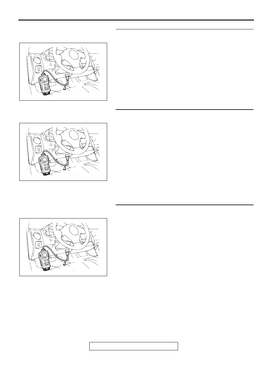
STEP 2. Using scan tool MB991502, check data list item 13:
Intake Air Temperature Sensor.
(1) Turn the ignition switch to the "ON" position.
(2) Set scan tool MB991502 to the data reading mode for item
13, Intake Air Temperature Sensor.
•
The intake air temperature and temperature shown with
the scan tool should approximately match.
(3) Turn the ignition switch to the "LOCK" (OFF) position.
Q: Is the sensor operating properly?
YES : Go to Step 3.
NO : Refer to, DTC P0111
−
Intake Air Temperature Circuit
Range/Performance Problem (
STEP 3. Using scan tool MB991502, check data list item 21:
Engine Coolant Temperature Sensor.
(1) Turn the ignition switch to the "ON" position.
(2) Set scan tool MB991502 to the data reading mode for item
21, Engine Coolant Temperature Sensor.
•
The engine coolant temperature and temperature
shown with the scan tool should approximately match.
(3) Turn the ignition switch to the "LOCK" (OFF) position.
Q: Is the sensor operating properly?
YES : Go to Step 4.
NO : Refer to, DTC P0115
−
Engine Coolant Temperature
Circuit High Input (
), DTC P0116
−
Engine
Coolant Temperature Circuit Range/Performance
Problem (
), DTC P0117
−
Engine Coolant
Temperature Circuit Low Input (
STEP 4. Using scan tool MB991502, check data list item 25:
Barometric Pressure Sensor.
(1) Turn the ignition switch to the "ON" position.
(2) Set scan tool MB991502 to the data reading mode for item
25, Barometric Pressure Sensor.
•
When altitude is 0 m(0 foot), 101 kPa.
•
When altitude is 600 m(1,969 feet), 95 kPa.
•
When altitude is 1,200 m(3,937 feet), 88 kPa.
•
When altitude is 1,800 m(5,906 feet), 81 kPa.
(3) Turn the ignition switch to the "LOCK" (OFF) position.
Q: Is the sensor operating properly?
YES : Go to Step 5.
NO : Refer to, DTC P0107
−
Barometric Pressure Circuit
Low Input (
), DTC P0108
−
Barometric
Pressure Circuit High Input (
AKX01177
16 PIN
MB991502
AB
AKX01177
16 PIN
MB991502
AB
AKX01177
16 PIN
MB991502
AB
MULTIPORT FUEL INJECTION (MFI) DIAGNOSIS
TSB Revision
MULTIPORT FUEL INJECTION (MFI) <2.4L ENGINE>
13A-160
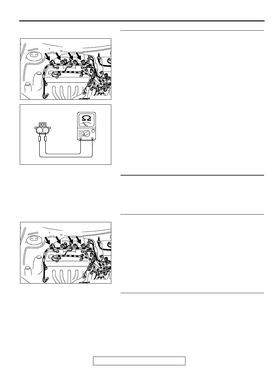
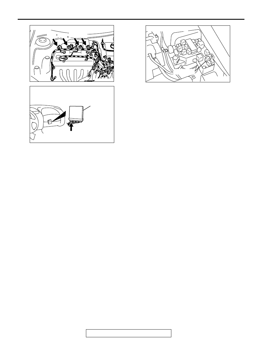
STEP 5. Check the injector.
(1) Disconnect each injector connector.
(2) Measure the resistance between injector side connector
terminal 1 and 2.
Standard value: 13
−
16 ohm [at 20
°
C (68
°
F)]
Q: Is the resistance standard value?
YES : Go to Step 6.
NO : Replace the injector. Then go to Step 8.
STEP 6. Check the fuel pressure.
Refer to, Fuel Pressure Test (
Q: Is the fuel pressure normal?
YES : Go to Step 7.
NO : Repair or replace it. Then go to Step 8.
STEP 7. Replace the injector.
(1) Replace the injector.
(2) Carry out a test drive with the drive cycle pattern. Refer to,
Procedure 2
−
Fuel Trim Monitor (
(3) Check the diagnostic trouble code (DTC).
Q: Is the DTC P0172 is output?
YES : Replace the ECM or PCM. Then go to Step 8.
NO : The inspection is complete.
STEP 8. Test the OBD- II drive cycle.
(1) Carry out a test drive with the drive cycle pattern. Refer to,
Procedure 2
−
Fuel Trim Monitor (
(2) Check the diagnostic trouble code (DTC).
Q: Is the DTC P0172 is output?
YES : Retry the troubleshooting.
NO : The inspection is complete.
AK000273AB
AK000273
CONNECTOR : B-01, B-02, B-05, B-06
B-01 B-02 B-05 B-06
AK000559
2
1
INJECTOR SIDE
CONNECTOR
AB
AK000273AB
AK000273
CONNECTOR : B-01, B-02, B-05, B-06
B-01 B-02 B-05 B-06
MULTIPORT FUEL INJECTION (MFI) DIAGNOSIS
TSB Revision
MULTIPORT FUEL INJECTION (MFI) <2.4L ENGINE>
13A-161
DTC P0201: Injector Circuit Malfunction
−
Cylinder 1, DTC P0202: Injector Circuit Malfunction
−
Cylinder 2, DTC
P0203: Injector Circuit Malfunction
−
Cylinder 3, DTC P0204: Injector Circuit Malfunction - Cylinder 4
AK000661
3 4
1 2
RED
-
WHITE
RED
-
WHITE
RED
-
WHITE
RED
RED
RED
RED
RED
YELL
OW
-
BL
UE
YELL
OW
-
RED
YELL
OW
-
BL
ACK
GREEEN-
YELL
OW
BATTERY
A-21X
MFI
RELAY
INJECTOR
NO.1
INJECTOR
NO.2
INJECTOR
NO.3
INJECTOR
NO.4
B-01
B-02
B-05
B-06
1
1
1
1
1
2
2
2
2
2
3
4
ENGINE CONTROL
MODULE(ECM)<M/T>
OR
POWERTRAIN CONTROL
MODULE(PCM)<A/T>
1
14<M/T>
9<A/T>
2<M/T>
24<A/T>
15<M/T>
2<A/T>
C-49<M/T>
(MU803773)
C-50<A/T>
(MU803784)
1
14
4
19
5
22
6
17
8
15
9
18
7
20
16
2
13
12
23 24 25 26
21
3
10 11
2
3 4
5 6
7 8
9
11 12 13 14 15 16 17 18 19 20
30
21 22 23
24 25
26 27 28 29
3132 33
34 35
1
10
2
1
2
1
2
1
2
1
MULTIPORT FUEL INJECTION (MFI) DIAGNOSIS
TSB Revision
MULTIPORT FUEL INJECTION (MFI) <2.4L ENGINE>
13A-162
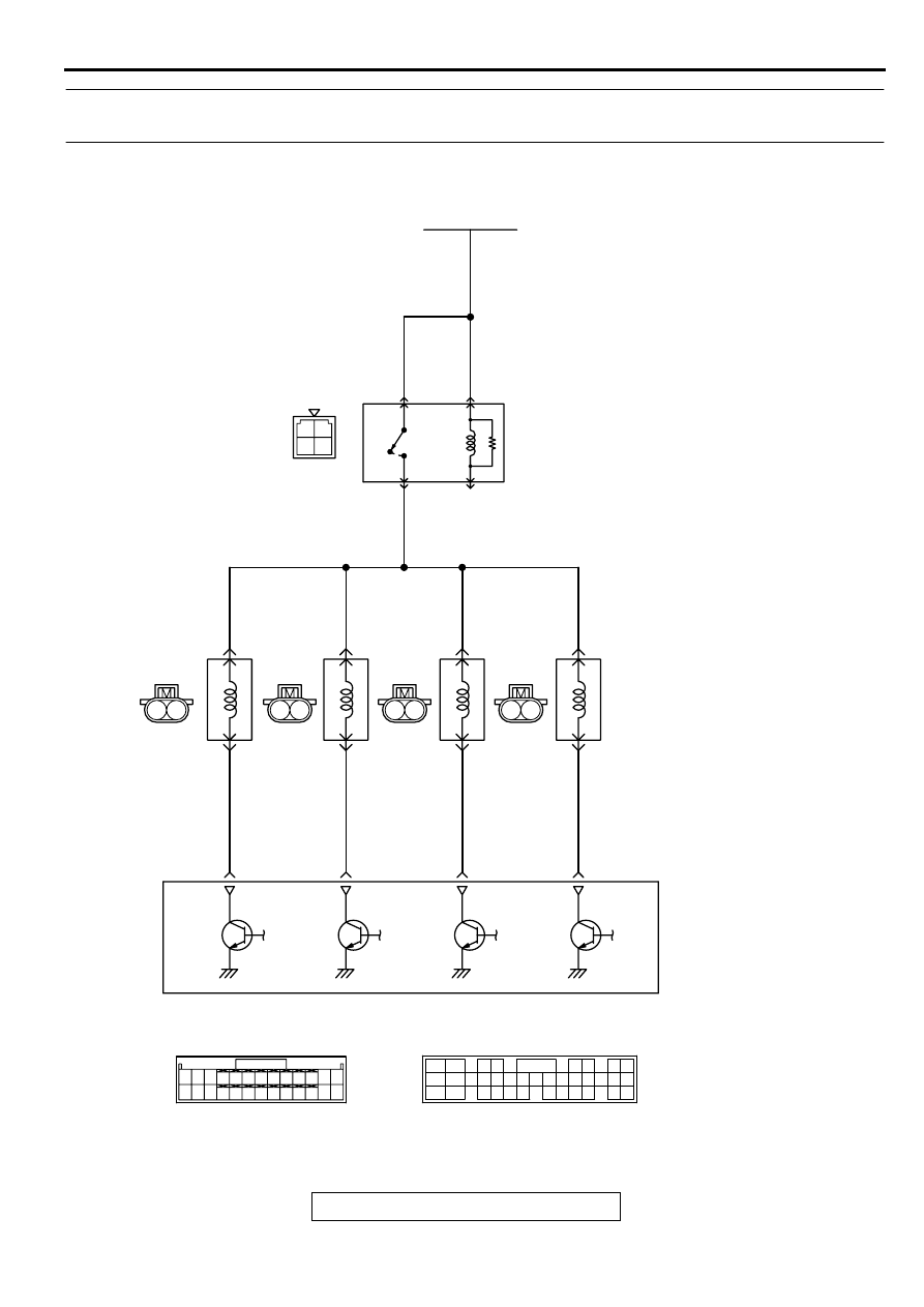
CIRCUIT OPERATION
•
The injector power is supplied from the MFI relay
(terminal 1).
•
The ECM <M/T> or PCM <A/T> controls the
injector by turning the power transistor in the
ECM <M/T> or PCM <A/T> "ON" and "OFF."
TECHNICAL DESCRIPTION
•
The amount of fuel injected by the injector is
controlled by the amount of continuity time the
coil is grounded by the ECM <M/T> or PCM <A/
T>.
•
A surge voltage is generated when the injectors
are driven and the current flowing to the injector
coil is shut off.
•
The ECM <M/T> or PCM <A/T> checks this
surge voltage.
DTC SET CONDITIONS
Check Conditions
•
Engine speed is lower than 1,000 r/min.
•
Throttle position sensor output voltage is lower
than 1.16 volts.
Judgment Criteria
•
Injector coil surge voltage (battery positive
voltage + 2 volts) has not been detected for two
seconds.
TROUBLESHOOTING HINTS (The most likely
causes for this code to be set are:)
•
Injector failed.
•
Open or shorted injector circuit, or loose
connector.
•
ECM failed. <M/T>
•
PCM failed. <A/T>
DIAGNOSIS
Required Special Tools
MB991502: Scan Tool (MUT-II)
MB991348: Test Harness
AK000273AB
AK000273
CONNECTOR : B-01, B-02, B-05, B-06
B-01 B-02 B-05 B-06
AK000280
C-49,C-50
ECM<M/T>
OR
PCM<A/T>
CONNECTORS:C-49<M/T>,C-50<A/T>
BC
AK000226
AK000226AB
CONNECTOR : A-21X
MFI RELAY
Нет комментариевНе стесняйтесь поделиться с нами вашим ценным мнением.
Текст