Mitsubishi Eclipse / Eclipse Spyder (2000-2002). Service and repair manual — part 357
CHARGING SYSTEM
TSB Revision
ENGINE ELECTRICAL
16-5
STEP 3.
Q: Does the charging warning light brightly when the
ignition switch is turned on?
YES : Go to Step 4.
NO :
•
Check the ignition switch. (Refer to GROUP 54A,
Ignition switch
•
Check for burnt-out charging warning light.
•
Check the generator. (Refer to Generator
−
Disassembly and assembly
−
Inspection
•
Check the charging warning light-related circuits.
STEP 4.
Q: Does the charging warning light go out after starting the
engine?
YES : Go to Step 5.
NO : Check the generator (Refer to Generator
−
Disassembly and assembly
−
Inspection
STEP 5.
Q: Is an oscilloscope available?
YES : Go to Step 6.
NO : Go to Step 7.
STEP 6.
Q: Dose the oscilloscope show a normal wave pattern?
(Refer to Charging system
−
Wave pattern check using a
oscilloscope
YES : Go to Step 7.
NO : Check the generator. (Refer to Generator
−
Disassembly and assembly
−
Inspection
STEP 7.
•
Engine: 2,500 r/min
•
Headlight: ON (high beam)
•
Voltage between generator terminal B and the positive
battery terminal
OK: 0.5V or less
•
Voltage between the negative battery terminal and
generator body
OK: 0.5V or less
Q: Are the generator output line and ground line in good
condition?
YES : Go to Step 8.
NO : Check the generator output line and ground line.
CHARGING SYSTEM
TSB Revision
ENGINE ELECTRICAL
16-6
STEP 8.
Q: Is the output current normal? (Refer to Charging system
−
On vehicle service
−
Output current test
.)
YES : Go to Step 9.
NO : Check the generator (Refer to Generator
−
Disassembly and assembly
−
Inspection
STEP 9.
Q: Is the regulated voltage normal? (Refer to Charging
system
−
On vehicle service - Regulated voltage test
.)
YES : Go to Step 10.
NO : Check the generator (Refer to Generator
−
Disassembly and assembly
−
Inspection
STEP 10.
Q: Is the voltage drops in the generator output line
normal?
YES : Generator is normal. Check other systems.
NO : Check the output line.
ON-VEHICLE SERVICE
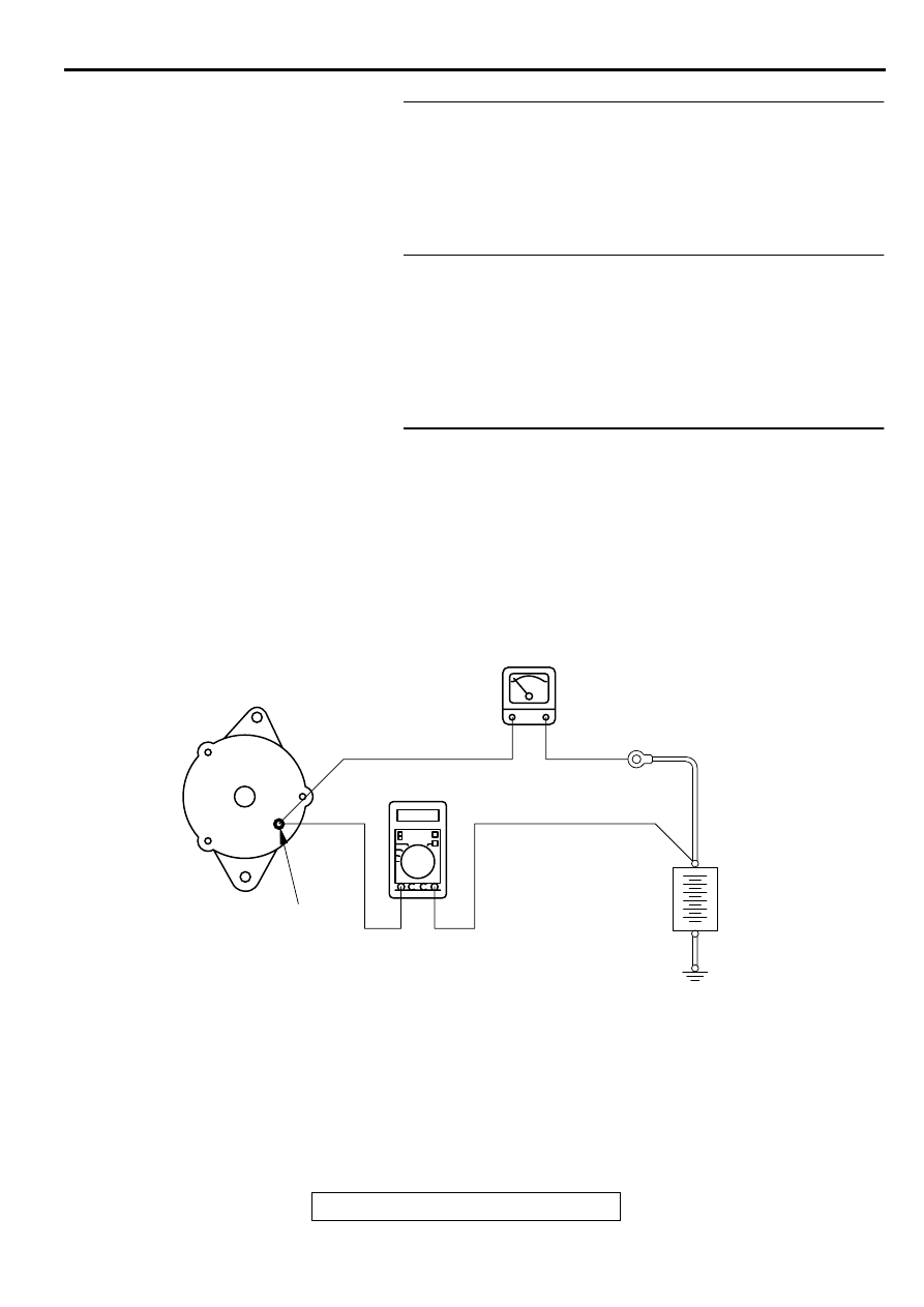
GENERATOR OUTPUT LINE VOLTAGE DROP TEST
M1161000900067
Required Special Tool:
MB991502: Scan Tool (MUT-II)
This test determines whether the wiring from the
generator "B" terminal to the positive battery terminal
(including the fusible link) is in good condition or not:
1. Always be sure to check the following before the
test.
•
Generator installation
•
Generator drive belt tension (Refer to GROUP
00, Maintenance Service
−
Drive Belts
•
Fusible link
•
Abnormal noise from the generator while the
engine is running
AKX00185
GENERATOR
AMMETER
VOLTMETER
(DIGITAL-TYPE)
BATTERY
+
-
"B"TERMINAL
AB
CHARGING SYSTEM
TSB Revision
ENGINE ELECTRICAL
16-7
2. Turn the ignition switch to the "LOCK" (OFF)
position.
WARNING
Battery posts, terminals and related
accessories contain lead and lead
compounds. WASH HANDS AFTER
HANDLING.
3. Disconnect the negative battery cable.
4. Disconnect the generator output wire from the
generator "B" terminal and connect a DC test
ammeter with a range of 0
−
100 A in series
between the "B" terminal and the disconnected
output wire. (Connect the positive lead of the
ammeter to the "B" terminal, and then connect the
negative lead of the ammeter to the disconnected
output wire.)
NOTE: A clamp-type ammeter which enables
measurements to be taken without disconnecting
the generator output wire is recommended. If the
voltage may have dropped due to a bad
connection at generator "B" terminal and the
generator "B" terminal is loosened when the test
ammeter is connected, the connection will be
completed at this time and the possibility of
finding the problems will be reduced.
5. Connect a digital-type voltmeter between the
generator "B" terminal and the positive battery
terminal. (Connect the positive lead of the
voltmeter to the "B" terminal, and then connect the
negative lead of the voltmeter to the positive
battery cable.)
WARNING
Battery posts, terminals and related
accessories contain lead and lead
compounds. WASH HANDS AFTER
HANDLING.
6. Reconnect the negative battery cable.
7. Connect a tachometer or scan tool MB991502.
8. Leave the hood open.
9. Start the engine.
10.With the engine running at 2,500 r/min, turn the
headlights and other lights on and off to adjust the
generator load so that the value displayed on the
ammeter is slightly above 30 A.
Limit value: maximum 0.3 V
NOTE: When the generator output is high and the
value displayed on the ammeter does not
decrease to 30A, set the value to 40A. Read the
value displayed on the voltmeter at this time.
In this case the limit value becomes maximum
0.4V.
Adjust the engine speed by gradually decreasing
it until the value displayed on the ammeter is 30
A. Take a reading of the value displayed on the
voltmeter at this time.
11.If the value displayed on the voltmeter is above
the limit value, there is probably a malfunction in
the generator output wire. Check the wiring
between the generator "B" terminal and the
positive battery terminal (including fusible link).
If a terminal is not sufficiently tight or if the
harness has become discolored due to
overheating, repair and then test again.
12.After the test, run the engine at idle.
13.Turn off all lights and turn the ignition switch to the
"LOCK" (OFF) position.
14.Disconnect the tachometer or scan tool
MB991502.
WARNING
Battery posts, terminals and related
accessories contain lead and lead
compounds. WASH HANDS AFTER
HANDLING.
15.Disconnect the negative battery cable.
16.Disconnect the ammeter and voltmeter and
tachometer.
17.Connect the generator output wire to the
generator "B" terminal.
WARNING
Battery posts, terminals and related
accessories contain lead and lead
compounds. WASH HANDS AFTER
HANDLING.
18.Connect the negative battery cable.
CHARGING SYSTEM
TSB Revision
ENGINE ELECTRICAL
16-8
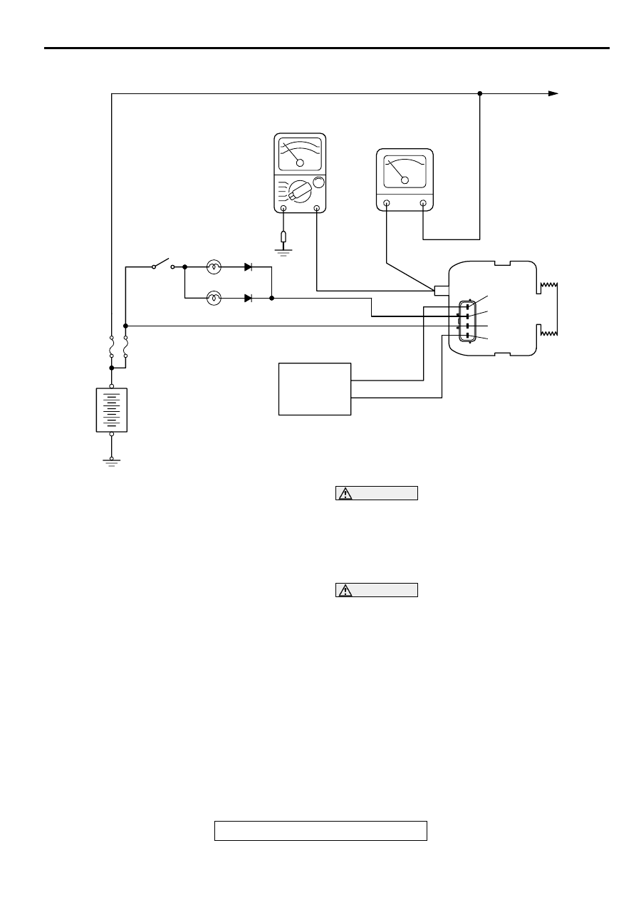
OUTPUT CURRENT TEST
M1161001000067
Required Special Tool:
MB991502: Scan Tool (MUT-II)
This test determines whether the generator outputs
normal current.
1. Before the test, always be sure to check the
following.
•
Generator installation
•
Battery (Refer to GROUP 54A, Battery
−
On-
vehicle Service
−
Battery Check
NOTE: The battery to be used should be slightly
discharged. The load in a fully-charged battery
will be insufficient and the test may not be able to
be carried out correctly.
•
Generator drive belt tension (Refer to GROUP
00, Maintenance Service
−
Drive Belts
•
Fusible link
•
Abnormal noise from the generator while the
engine is running
2. Turn the ignition switch to the "LOCK" (OFF)
position.
WARNING
Battery posts, terminals and related
accessories contain lead and lead
compounds. WASH HANDS AFTER
HANDLING.
3. Disconnect the negative battery cable.
WARNING
Never use clips to connect the line. Loose
connections (e.g. using clips) will lead to a
serious accident because of high current.
4. Disconnect the generator output wire from the
generator "B" terminal and connect a DC test
ammeter with a range of 0
−
100 A in series
between the "B" terminal and the disconnected
output wire. (Connect the positive lead of the
ammeter to the "B" terminal, and then connect the
negative lead of the ammeter to the disconnected
output wire.)
NOTE: A clamp-type ammeter which enables
measurements to be taken without disconnecting
the generator output wire is recommended.
AKX01214
VOLTMETER
AMMETER
LOAD
CHARGING
WARNING LIGHT
IGNITION
SWITCH
INDICATOR LAMP
(BRAKE WARNING LIGHT, etc.)
BATTERY
+
-
PCM<A/T>
GENERATOR
FR
L
S
G
AC
Нет комментариевНе стесняйтесь поделиться с нами вашим ценным мнением.
Текст