Mitsubishi Eclipse / Eclipse Spyder (2000-2002). Service and repair manual — part 356
16-1
GROUP 16
CONTENTS
CHARGING SYSTEM . . . . . . . .
GENERAL DESCRIPTION . . . . . .
SPECIAL TOOL . . . . . . . . . . . . . . .
CHARGING SYSTEM DIAGNOSIS
ON-VEHICLE SERVICE. . . . . . . . .
GENERATOR OUTPUT LINE VOLTAGE
DROP TEST . . . . . . . . . . . . . . . . . . . . .
OUTPUT CURRENT TEST . . . . . . . . . .
REGULATED VOLTAGE TEST. . . . . . .
WAVE PATTERN CHECK USING AN
OSCILLOSCOPE. . . . . . . . . . . . . . . . . .
GENERATOR ASSEMBLY . . . . . .
REMOVAL AND INSTALLATION . . . . .
DISASSEMBLY AND ASSEMBLY. . . . .
INSPECTION . . . . . . . . . . . . . . . . . . . . .
STARTING SYSTEM . . . . . . . . .
GENERAL DESCRIPTION . . . . . .
STARTING SYSTEM DIAGNOSIS
STARTER MOTOR ASSEMBLY . .
REMOVAL AND INSTALLATION . . . . .
INSPECTION . . . . . . . . . . . . . . . . . . . . .
DISASSEMBLY AND ASSEMBLY. . . . .
INSPECTION . . . . . . . . . . . . . . . . . . . . .
IGNITION SYSTEM . . . . . . . . .
GENERAL DESCRIPTION . . . . . . .
SPECIAL TOOLS . . . . . . . . . . . . . .
ON-VEHICLE SERVICE . . . . . . . . .
SPARK PLUG CABLE TEST . . . . . . . . .
IGNITION COIL CHECK . . . . . . . . . . . .
IGNITION COIL POWER TRANSISTOR
CONTINUITY CHECK . . . . . . . . . . . . . .
IGNITION FAILURE SENSOR CHECK .
SPARK PLUG CABLE RESISTANCE
CHECK . . . . . . . . . . . . . . . . . . . . . . . . . .
SPARK PLUG TEST . . . . . . . . . . . . . . .
SPARK PLUG CHECK AND CLEANING
CAMSHAFT POSITION SENSOR CHECK
CRANK ANGLE SENSOR CHECK . . . .
IGNITION SECONDARY VOLTAGE
WAVE PATTERN CHECK USING
AN OSCILLOSCOPE . . . . . . . . . . . . . . .
IGNITION PRIMARY VOLTAGE WAVE
PATTERN CHECK . . . . . . . . . . . . . . . . .
IGNITION COIL. . . . . . . . . . . . . . . .
REMOVAL AND INSTALLATION
<2.4L ENGINE> . . . . . . . . . . . . . . . . . . .
DISTRIBUTOR ASSEMBLY. . . . . .
REMOVAL AND INSTALLATION
<3.0L ENGINE> . . . . . . . . . . . . . . . . . . .
DISASSEMBLY AND ASSEMBLY . . . . .
16-2
CAMSHAFT POSITION SENSOR .
REMOVAL AND INSTALLATION
<2.4L ENGINE> . . . . . . . . . . . . . . . . . . .
CRANKSHAFT POSITION SENSOR
REMOVAL AND INSTALLATION
<2.4L ENGINE> . . . . . . . . . . . . . . . . . . .
REMOVAL AND INSTALLATION
<3.0L ENGINE> . . . . . . . . . . . . . . . . . . .
KNOCK SENSOR . . . . . . . . . . . . .
REMOVAL AND INSTALLATION
<2.4L ENGINE> . . . . . . . . . . . . . . . . . . .
REMOVAL AND INSTALLATION
<3.0L ENGINE> . . . . . . . . . . . . . . . . . . .
SPECIFICATIONS . . . . . . . . . .
FASTENER TIGHTENING
SPECIFICATIONS . . . . . . . . . . . . .
GENERAL SPECIFICATIONS . . . .
SERVICE SPECIFICATIONS . . . . .
CHARGING SYSTEM
TSB Revision
ENGINE ELECTRICAL
16-3
.
C H A R G IN G SYSTEM
GENERAL DESCRIPTION
M1161000100072
The charging system charges the battery with the
generator output to keep the battery charged at a
constant level during varying electrical load.
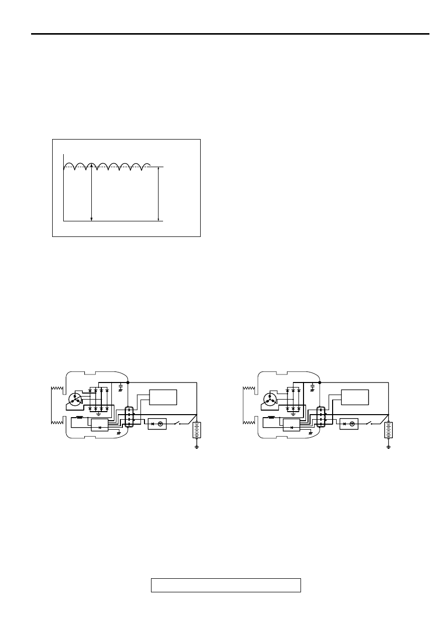
Operation
Rotation of the excited field coil generates AC
voltage in the stator.
This alternating current is rectified through diodes to
DC voltage having a waveform shown in the
illustration at left.
The average output voltage fluctuates slightly with
the generator load condition.
When the ignition switch is turned on, current flows in
the field coil and initial excitation of the field coil
occurs.
When the stator coil begins to generate power after
the engine is started, the field coil is excited by the
output current of the stator coil.
The generator output voltage rises as the field
current increases and it falls as the field current
decreases. When the battery positive voltage
(generator S terminal voltage) reaches a regulated
voltage of approximately 14.4V, the field current is
cut off. When the battery positive voltage drops
below the regulated voltage, the voltage regulator
regulates the output voltage to a constant level by
controlling the field current.
In addition, when the field current is constant, the
generator output voltage rises as the engine speed
increases.
AKX00183
VOLTAGE
TIME
APPROXIMATELY
14.4V
AB
AK000621
GENERATOR
GENERATOR
<2.4L ENGINE>
<3.0L ENGINE>
B
B
STATOR
COIL
STATOR
COIL
ECM<M/T>
PCM<A/T>
ECM<M/T>
PCM<A/T>
G
S
L
FR
G
S
L
FR
VOLTAGE REGULATOR
VOLTAGE REGULATOR
CHARGING
WARNING
LIGHT
CHARGING
WARNING
LIGHT
IGNITION
SWITCH
IGNITION
SWITCH
BATTERY
FIELD COIL
FIELD COIL
−
BATTERY
−
AC
+
+
CHARGING SYSTEM
TSB Revision
ENGINE ELECTRICAL
16-4
SPECIAL TOOLS
M1161000600055
CHARGING SYSTEM DIAGNOSIS
M1161000700063
TROUBLESHOOTING HINTS
1. Charging warning light does not go on when the ignition
switch is turned to ON, before the engine starts.
•
Check the bulb.
2. Charging warning light does not switch off after the engine
starts.
•
Check the IC voltage regulator inside the generator.
3. Discharged or overcharged battery.
•
Check the IC voltage regulator inside the generator.
4. The charging warning light illuminates dimly.
•
Check the diode (inside the combination meter) for a short-
circuit.
TROUBLESHOOTING GUIDE
The charging system troubleshooting guide is shown in the
following chart.
STEP 1.
Q: Is the battery in good condition? (Refer to GROUP 54A,
Battery
−
On-vehicle Service - Battery Check
YES : Go to Step 2.
NO : Charge or replace the battery.
STEP 2.
Q: Is the generator drive belt in good condition? (Refer to
GROUP 00, Maintenance Service - Drive Belts
YES : Go to Step 3.
NO : Adjust the belt tension or replace the belt.
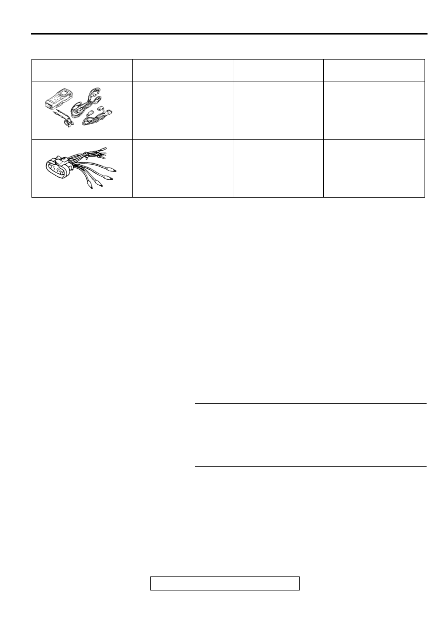
TOOL
TOOL NUMBER AND
NAME
SUPERSESSION
APPLICATION
MB991502
Scan tool (MUT-II)
MB991496-OD
Checking of engine idle
speed
MB991519
Generator harness
connector
Tool not available
Checking of generator (S
terminal voltage)
B991502
Нет комментариевНе стесняйтесь поделиться с нами вашим ценным мнением.
Текст