Mitsubishi Eclipse / Eclipse Spyder (2000-2002). Service and repair manual — part 358
CHARGING SYSTEM
TSB Revision
ENGINE ELECTRICAL
16-9
5. Connect a voltmeter with a range of 0
−
20 V
between the generator "B" terminal and the
ground. (Connect the positive lead of the
voltmeter to the "B" terminal, and then connect the
negative lead of the voltmeter to the ground.)
WARNING
Battery posts, terminals and related
accessories contain lead and lead
compounds. WASH HANDS AFTER
HANDLING.
6. Connect the negative battery cable.
7. Connect a tachometer or scan tool MB991502.
8. Leave the hood open.
9. Check to be sure that the reading on the voltmeter
is equal to the battery positive voltage.
NOTE: If the voltage is 0 V, the cause is probably
an open circuit in the wire or fusible link between
the generator "B" terminal and the battery positive
terminal.
10.After turning the light switch on and turning on the
headlights, start the engine.
NOTE: Because the current from the battery will
soon drop after the engine is started, step 11
should be carried out as quickly as possible in
order to obtain the maximum current output value.
11.Immediately after setting the headlights to high
beam and turning the heater blower switch to the
high revolution position, increase the engine
speed to 2,500 r/min and read the maximum
current output value displayed on the ammeter.
Limit value: 70% of nominal current output
NOTE: For the nominal current output, refer to the
Generator Specifications.
NOTE: The current output value will depend on
the electrical load and the temperature of the
generator body.
NOTE: If the electrical load is small while testing,
the specified level of current may not be output
even though the generator is normal. In such
cases, increase the electrical load by leaving the
headlights turned on for some time to discharge
the battery or by using the lighting system in
another vehicle, and then test again.
NOTE: The specified level of current also may not
be output if the temperature of the generator body
or the ambient temperature is too high. In such
cases, cool the generator and then test again.
12.The reading on the ammeter should be above the
limit value. If the reading is below the limit value
and the generator output wire is normal, remove
the generator from the engine and check the
generator.
13.Run the engine at idle speed after the test.
14.Turn the ignition switch to the "LOCK" (OFF)
position.
15.Disconnect the tachometer or scan tool
MB991502.
WARNING
Battery posts, terminals and related
accessories contain lead and lead
compounds. WASH HANDS AFTER
HANDLING.
16.Disconnect the negative battery cable.
17.Disconnect the ammeter and voltmeter and
tachometer.
18.Connect the generator output wire to the
generator "B" terminal.
WARNING
Battery posts, terminals and related
accessories contain lead and lead
compounds. WASH HANDS AFTER
HANDLING.
19.Connect the negative battery cable.Before the
test, always be sure to check the following.
CHARGING SYSTEM
TSB Revision
ENGINE ELECTRICAL
16-10
REGULATED VOLTAGE TEST
M1161001100064
Required Special Tools:
•
MB991502: Scan Tool (MUT-II)
•
MB991519: Generator Harness Connector
This test determines whether the voltage regulator is
correctly controlling the generator output voltage.
1. Always be sure to check the following before the
test:
•
Generator installation
•
Check to be sure that the battery installed in the
vehicle is fully charged. (Refer to GROUP 54A,
Battery
−
On-vehicle Service
−
Battery Check
•
Generator drive belt tension (Refer to GROUP
00, Maintenance Service
−
Drive Belts
•
Fusible link
•
Abnormal noise from the generator while the
engine is running
2. Turn the ignition switch to the "LOCK" (OFF)
position.
WARNING
Battery posts, terminals and related
accessories contain lead and lead
compounds. WASH HANDS AFTER
HANDLING.
3. Disconnect the negative battery cable.
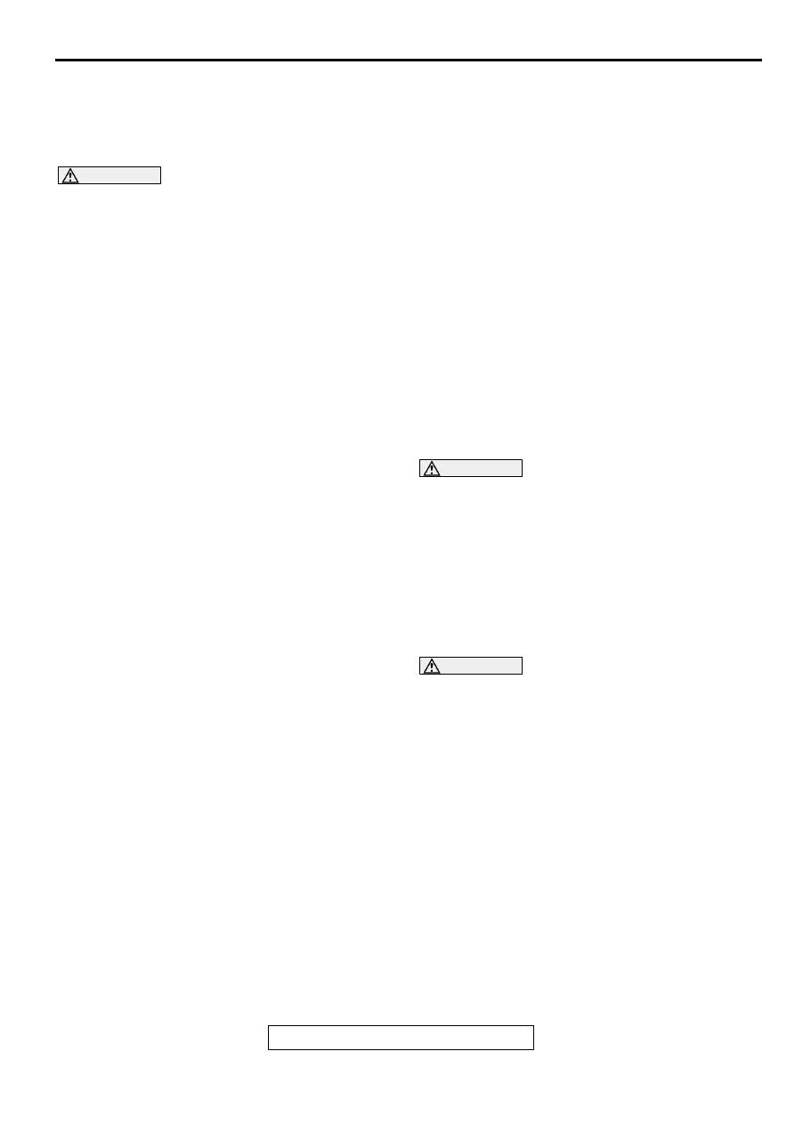
4. Use the special tool (Generator harness
connector: MB991519) to connect a digital-type
voltmeter between the generator "S" terminal and
the ground. (Connect the positive lead of the
voltmeter to the "S" terminal, and then connect the
negative lead of the voltmeter to a secure ground
or to the negative battery terminal.)
5. Disconnect the generator output wire from the
generator "B" terminal.
6. Connect a DC test ammeter with a range of 0
−
100 A in series between the "B" terminal and the
disconnected output wire. (Connect the positive
load of the ammeter to the "B" terminal, and then
connect the negative lead of the ammeter to the
disconnected output wire.)
WARNING
Battery posts, terminals and related
accessories contain lead and lead
compounds. WASH HANDS AFTER
HANDLING.
7. Reconnect the negative battery cable.
8. Connect a tachometer or the scan tool
MB991502.
9. Turn the ignition switch to the "ON" position and
check that the reading on the voltmeter is equal to
the battery positive voltage.
NOTE: If the voltage is 0 V, the cause is probably
an open circuit in the wire or fusible link between
the generator "S" terminal and the battery positive
terminal.
10.Check to be sure that all lights and accessories
are off.
11.Start the engine.
12.Increase the engine speed to 2,500 r/min.
13.Read the value displayed on the voltmeter when
the current output by the generator becomes 10 A
or less.
AKX01215
LOAD
AMMETER
CHARGING
WARNING
LIGHT
IGNITION
SWITCH
BLACK
GENERATOR
INDICATOR LAMP
(BRAKE WARNING
LIGHT, etc.)
G
S
L
FR
BLUE
YELLOW
RED
VOLTMETER
(DIGITAL-TYPE)
BATTERY
+
-
PCM (A/T)
AC
MB991519
CHARGING SYSTEM
TSB Revision
ENGINE ELECTRICAL
16-11
14.If the voltage reading conforms to the value in the
voltage regulation table, then the voltage
regulator is operating normally.
If the voltage is outside the standard value, there
is a malfunction of the voltage regulator or the
generator (Refer to the following table).
15.After the test, lower the engine speed to the idle
speed.
16.Turn the ignition switch to the "LOCK" (OFF)
position.
WARNING
Battery posts, terminals and related
accessories contain lead and lead
compounds. WASH HANDS AFTER
HANDLING.
17.Disconnect the negative battery cable.
18.Disconnect the ammeter, voltmeter and
tachometer.
19.Connect the generator output wire to the
generator "B" terminal.
WARNING
Battery posts, terminals and related
accessories contain lead and lead
compounds. WASH HANDS AFTER
HANDLING.
20.Connect the negative battery cable.
VOLTAGE REGULATION TABLE
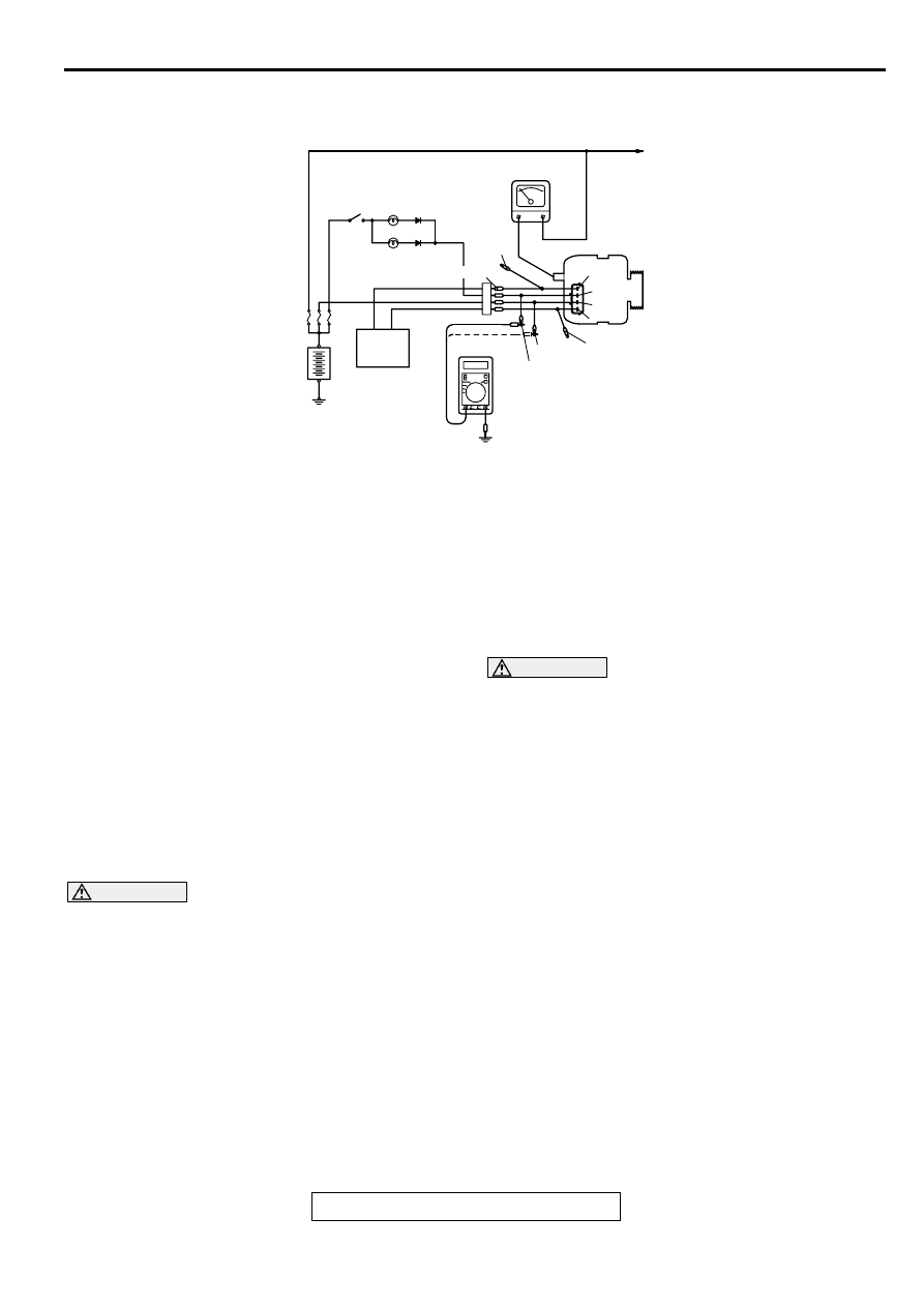
WAVE PATTERN CHECK USING AN
OSCILLOSCOPE
M1161001200049
MEASUREMENT METHOD
Connect the oscilloscope probe to the generator "B" terminal.
INSPECTION TERMINAL
VOLTAGE REGULATOR
AMBIENT TEMPERATURE
[
°
C(
°
F)]
STANDARD VALUE (V)
Terminal "S"
−
20 (
−
4)
14.2
−
15.4
20 (68)
13.9
−
14.9
60 (140)
13.4
−
14.5
80 (176)
13.1
−
14.5
AKX00188
GENERATOR
OSCILLOSCOPE
"B"TERMINAL
PROBE
AB
CHARGING SYSTEM
TSB Revision
ENGINE ELECTRICAL
16-12
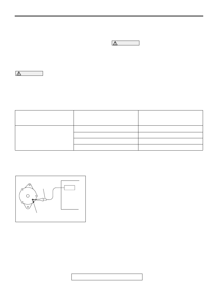
STANDARD WAVEFORM
NOTE: The voltage waveform of the generator "B" terminal can
undulate as shown at left. This waveform is produced when the
regulator operates according to fluctuations in the generator
load (current), and is normal for the generator.If the ripple
height is abnormally high (approximately 2 V or more during
idling), the wires between the generator B terminal and the
battery have broken due to fuse blowing, etc. The generator is
usually operating properly.
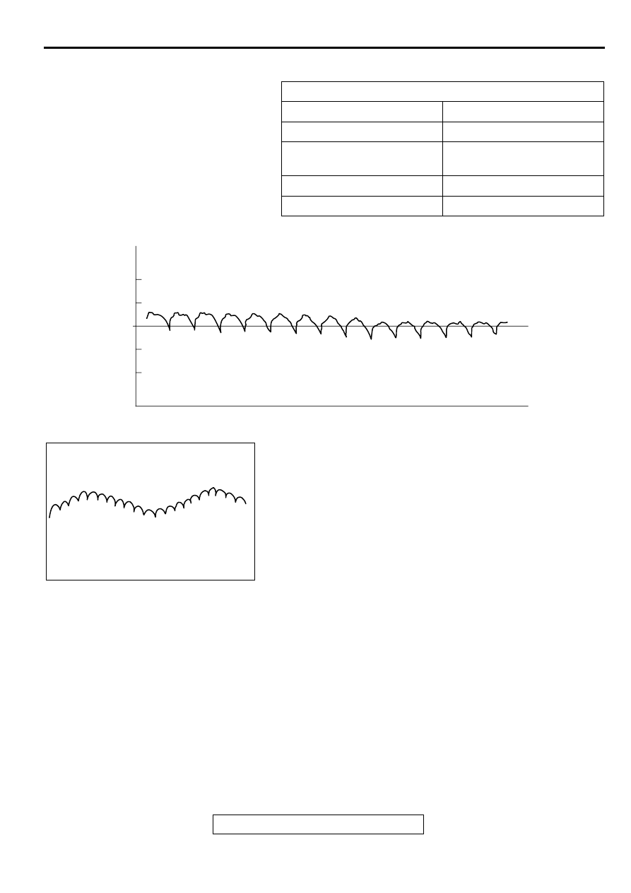
ABNORMAL WAVEFORMS EXAMPLES
NOTE: The size of the waveform patterns can differ greatly, depending on the adjustment of the variable
knob on the oscilloscope.
NOTE: Identification of abnormal waveforms is easier when there is a large output current (regulator is not
operating). (Waveforms can be observed when the headlights are illuminated.)
NOTE: Check the conditions of the charging indicator light (illuminated/not illuminated) also, and carry out a
total check.
Observation Conditions
FUNCTION
SPECIAL PATTERNS
Pattern height
Variable
Variable knob
Adjust while viewing the wave
pattern
Pattern selector
Raster
Engine revolutions
Curb idle speed
AKX00189
0.4
(V)
0.2
0
-0.2
-0.4
VOLTAGE AT
GENERATOR
"B"TERMINAL
TIME
AB
AKX00190
Нет комментариевНе стесняйтесь поделиться с нами вашим ценным мнением.
Текст