Mitsubishi Eclipse / Eclipse Spyder (2000-2002). Service and repair manual — part 658

REAR WIPER AND WASHER
TSB Revision
EXTERIOR
51-19
2. Windshield intermittent wiper interval adjusting knob
Measure the resistance value at terminal numbers 27 and
28. The resistance value should rise smoothly from
approximately 0
Ω
("FAST" position) to approximately 1 k
Ω
("SLOW" position).
R EAR W IPER A ND WA SHER
GENERAL DESCRIPTION
M1511000100138
OPERATION
Rear Wiper Operation
•
If the rear wiper and washer switch is turned to
the "INT" position with the ignition switch at
"ACC" or "ON" position, the ETACS-ECU causes
the rear wiper to operate continuously two times,
then intermittently at eight-second intervals.
•
If the selector lever is moved to the "R" position
when the rear wiper and washer switch is turned
the "INT" position and the ignition switch at
"ACC" or "ON" position, park/neutral position
switch "R" turns ON. One second later, the
ETACS-ECU causes the rear wiper to operate
two times continuously to ensure good rearward
visibility. The ETACS-ECU then causes the rear
wiper to again operate intermittently at eight-
second intervals.
Rear Washer Operation
•
If the rear wiper and washer switch is turned the
"WASHER" position with the ignition switch at
"ACC" or "ON" position, the rear washer ON
signal is sent to the ETACS-ECU, causing the
rear wiper signal to turn on after 0.9 seconds.
After the rear washer switch signal turns off, the
rear wiper signal turns off in three seconds.
•
If the rear wiper and washer switch is turned to
the "WASHER" position while the rear wiper is at
intermittent mode, the rear washer works for that
period when the washer switch remains on. Then
the rear wipers return to the intermittent mode.
REAR WIPER AND WASHER DIAGNOSIS
M1511000700118
The rear wiper and washer are controlled by ETACS-
ECU. For troubleshooting, refer to GROUP 54B,
SWS Diagnosis.
Windshield low-speed
wiper switch
23
−
30
Continuity
Windshield high-speed
wiper switch
21
−
23
Continuity
Windshield washer
switch
22
−
23
Continuity
SWITCH POSITION
TESTER
CONNECTION
SPECIFIED
CONDITION
REAR WIPER AND WASHER
TSB Revision
EXTERIOR
51-20
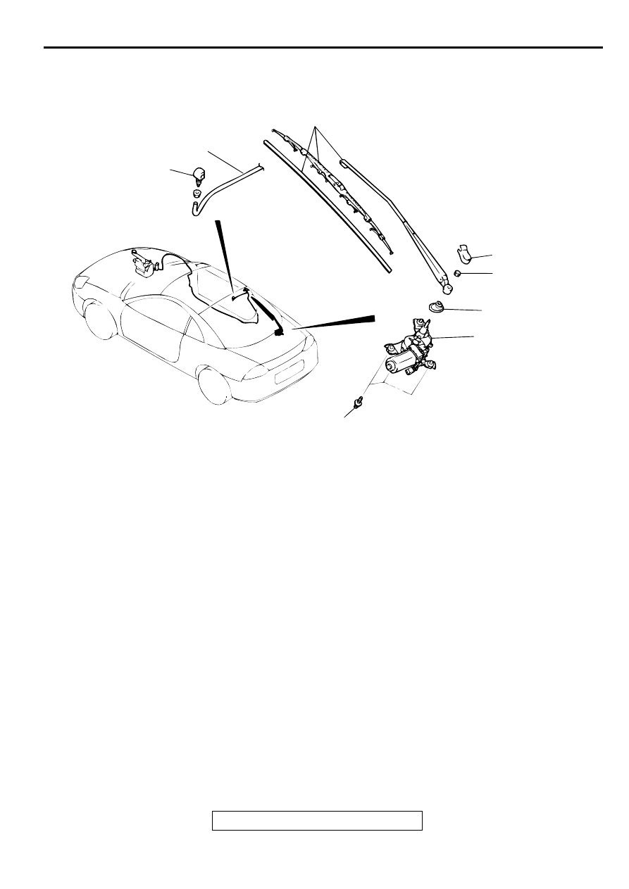
REMOVAL AND INSTALLATION
M1511008800045
NOTE: For removal and installation of the wiper and
washer switch, refer to GROUP 54A, Column switch
AC003327
AX0175AW
9.8 ± 2.0 N·m
87 ± 17 in-lb
1
3
4
4.9 ±0.7 N·m
43 ± 6 in-lb
2
5
6
AB
•
WASHER TANK ASSEMBLY AND
REAR WASHER MOTOR (REFER
TO GROUP 51,WINDSHIELD
WIPER AND WASHER
REAR WIPER MOTOR ASSEMBLY
REMOVAL STEPS
1. COVER
>>A<<
2. REAR WIPER ARM AND BLADE
ASSEMBLY
•
LIFTGATE LOWER TRIM (REFER
TO GROUP 42, LIFTGATE TRIM
.)
>>B<<
3. GROMMET
4. REAR WIPER MOTOR ASSEMBLY
REAR WASHER HOSE REMOVAL
STEPS
•
QUARTER TRIM, LOWER <RH>
(REFER TO GROUP 52A, TRIMS
.)
5. REAR WASHER HOSE
>>A<<
6. WASHER NOZZLE
REAR WIPER AND WASHER
TSB Revision
EXTERIOR
51-21
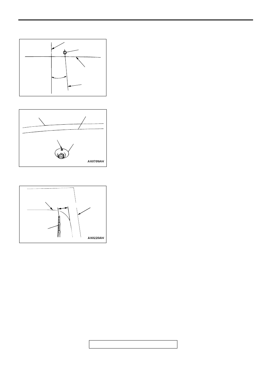
INSTALLATION SERVICE POINTS
>>A<< WASHER NOZZLE INSTALLATION
Install the washer nozzle in the specified direction.
>>B<< GROMMET INSTALLATION
Install the grommet so that the arrow points upwards.
>>C<< REAR WIPER ARM AND BLADE ASSEMBLY
INSTALLATION
Install the wiper blade so that the tip stops at the standard
position (standard value), and also so that the lower section of
the wiper blade enters the middle of the defogger pattern.
Standard value (A): 89
−
99 mm (3.5
±
3.9 inches)
AX0707AW
AC003636
DISCHARGE
DIRECTION
CERAMIC LINE
WASHER NOZZLE
GLASS CENTER LINE
AB
5
AC003637
GROMMET
ARROW
GLASS END LINE
CERAMIC LINE
AB
AC003638
CERAMIC LINE
WIPER ARM AND
BLADE ASSEMBLY
A
AB
GLASS END LINE
REAR WIPER AND WASHER
TSB Revision
EXTERIOR
51-22
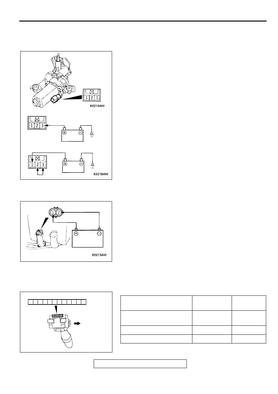
INSPECTION
REAR WIPER MOTOR CHECK
M1511012900067
Check the wiper motor after first disconnecting the wiring
harness connector, and with the wiper motor remaining
installed to the body.
Wiper Motor Operation
Connect a battery to the wiper motor as shown in the
illustration and inspect the motor operation.
Wiper Motor at Stop Position Operation
1. Run the wiper motor, disconnect the battery, and stop the
motor.
2. Reconnect the battery as shown in the illustration, and
confirm that after the motor starts turning it stops at the
automatic stop position.
REAR WASHER MOTOR CHECK
M1511013100064
1. With the washer motor installed to the washer tank, fill the
washer tank with water.
2. When the battery is connected as shown in the figure, check
that the washer squirts out strongly.
REAR WIPER AND WASHER SWITCH
INSPECTION
M1511009500058
AC003639
OPERATION CHECK
STOP POSITION CHECK
AB
AC003640
SWITCH POSITION
TERMINAL
CONNECTION
SPECIFIED
CONDITION
OFF
-
No continuity
Rear wiper switch ON
25 - 26
Continuity
Rear washer switch ON
25 - 29
Continuity
21
22
23
24
25
26
27
28
29
30
31
32
AC002017AC
UPPER SIDE
Нет комментариевНе стесняйтесь поделиться с нами вашим ценным мнением.
Текст