Mitsubishi Eclipse / Eclipse Spyder (2000-2002). Service and repair manual — part 657
WINDSHIELD WIPER AND WASHER
TSB Revision
EXTERIOR
51-15
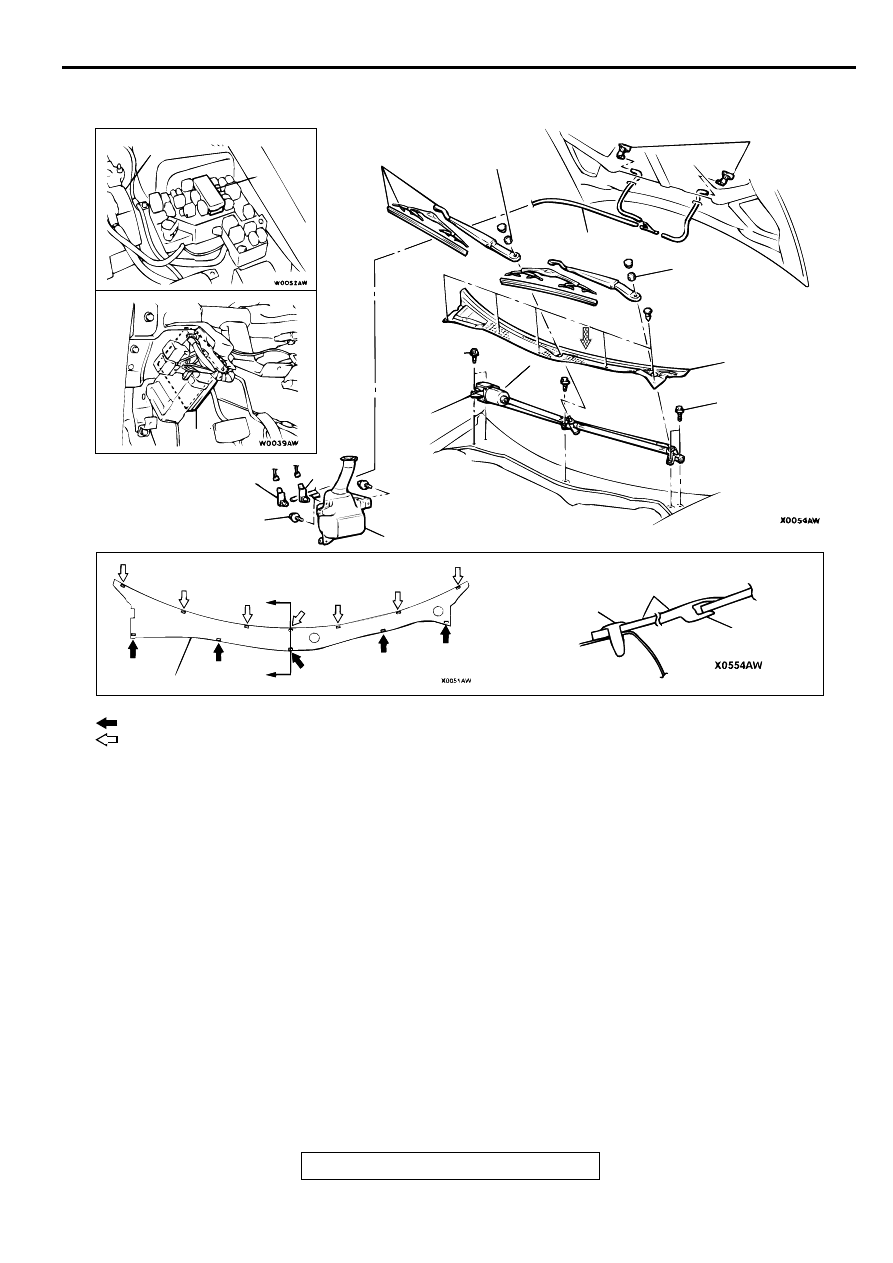
REMOVAL AND INSTALLATION
M1511007600059
NOTE: For removal and installation of the wiper and
washer switch, refer to GROUP 54A
Column switch.
AC003326
NOTE
: Clip position
: Claw position
AC003326
VIEW A
A
A
BATTERY
4
2
1
12 ± 1 N·m
100 ± 13 in-lb
8
5
5.0 ± 0.7 N·m
44 ± 6 in-lb
9
10
CLAW
CLIP
SECTION A – A
4
5.0 ± 0.7 N·m
44 ± 6 in-lb
4
13 ± 3 N·m
113 ± 26 in-lb
13 ± 3 N·m
113 ± 26 in-lb
7
3
VIEW A
AB
1. FRONT-ECU
2. ETACS-ECU
WIPER MOTOR AND LINK
ASSEMBLY REMOVAL STEPS
>>B<<
3. WIPER ARM AND BLADE
ASSEMBLY
4. FRONT DECK GARNISH
<<A>> >>A<<
5. WIPER MOTOR AND LINK
ASSEMBLY
WASHER NOZZLE REMOVAL
STEPS
•
FRONT SPLASH SHIELD
6.
WASHER HOSE
7.
WASHER NOZZLE
WASHER TANK REMOVAL STEPS
•
FRONT SPLASH SHIELD (REFER
TO GROUP 42, FENDER
•
FRONT BUMPER ASSEMBLY
(REFER TO GROUP51
.)
•
PASSENGER'S SIDE HEADLIGHT
(REFER TO GROUP 54A
•
WASHER FLUID DRAINING AND
REFILLING
6. WASHER HOSE
8. WASHER TANK ASSEMBLY
9. FRONT WINDSHIELD WASHER
MOTOR
10. REAR WINDSHIELD WASHER
MOTOR
WINDSHIELD WIPER AND WASHER
TSB Revision
EXTERIOR
51-16
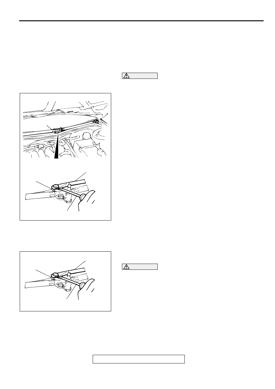
REMOVAL SERVICE POINT
<<A>> WIPER MOTOR AND LINK ASSEMBLY REMOVAL
1. Remove the five mounting bolts of the wiper motor and link
assembly and disconnect the connector.
2. To protect the windshield, apply duct tape to the entire
circumference of the glass near the wiper motor and link
assembly installation position.
CAUTION
Be careful not to damage the windshield glass when
removing the wiper motor and link assembly.
3. Use a flat-tipped screwdriver to disengage the driver's side
link from the center crank arm.
4. Remove the wiper motor and link assembly from the vehicle
body (the cowl) while being careful not to scratch the
windshield glass.
INSTALLATION SERVICE POINTS
>>A<< WIPER MOTOR AND LINK ASSEMBLY
INSTALLATION
1. Disengage the driver's side link from the center crank arm
when replacing with new one.
CAUTION
Be careful not to scratch the windshield glass when
installing the wiper motor and link assembly.
2. Install the wiper motor and link assembly to the vehicle body
(the cowl) while being careful not to scratch the windshield
glass.
AC001696
AX0607AW
WIPER MOTOR AND LINK
ASSEMBLY
DRIVER'S SIDE LINK
CENTER CRANK ARM
FLAT-TIPPED SCREWDRIVER
AB
BX0607AW
AC001697
DRIVER'S SIDE LINK
CENTER CRANK ARM
FLAT-TIPPED SCREWDRIVER
AB
WINDSHIELD WIPER AND WASHER
TSB Revision
EXTERIOR
51-17
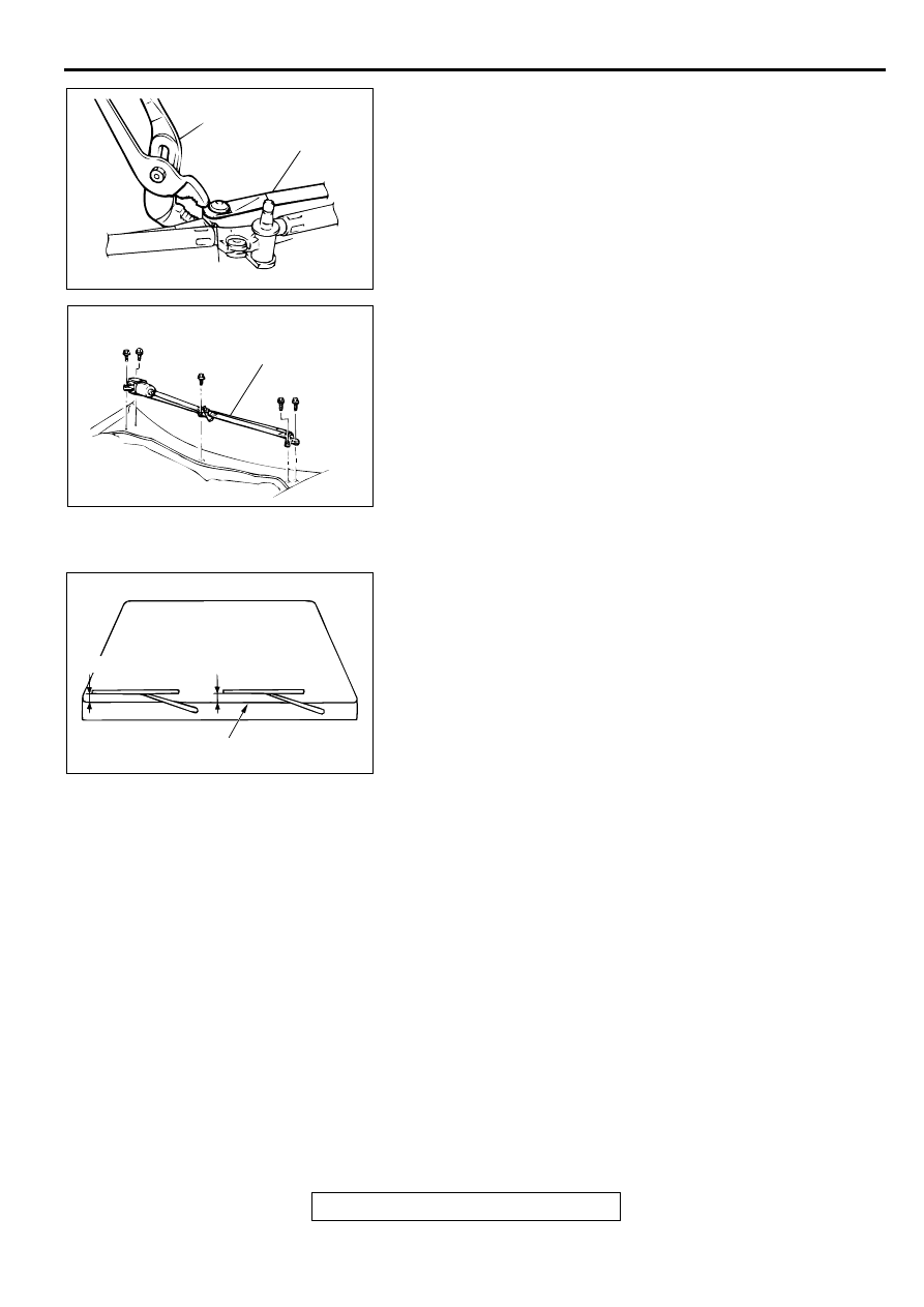
3. Use water pump pliers to engage securely the driver's side
link with the center crank arm.
4. Install the five mounting bolts in the shown order to install
the wiper motor and link assembly.
5. Secure the wiper motor and link assembly in the wiper park
position (Refer to, Wiper Motor Check
>>B<< WIPER ARM AND BLADE ASSEMBLY
INSTALLATION
Install the wiper blade at the specified position (standard
value).
Standard value:
Driver's side: 33
−
43 mm (1.3
−
1.7 inches)
Passenger's side: 38
−
48 mm (1.5
−
1.9 inches)
AX0708AW
AC001698
WATER PUMP PLIERS
DRIVER'S SIDE LINK
CENTER CRANK ARM
AB
AX0608AW
AC001699
BOLT INSTALLATION ORDER
1
2
3
4 5
WIPER MOTOR AND
LINK ASSEMBLY
AB
AC000427AC
DRIVER'S SIDE
PASSENGER'S SIDE
FRONT DECK GARNISH END
WINDSHIELD WIPER AND WASHER
TSB Revision
EXTERIOR
51-18
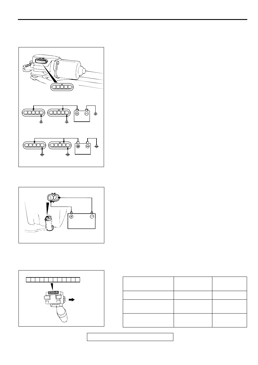
INSPECTION
FRONT WIPER MOTOR CHECK
M1511012600055
Check the wiper motor after disconnecting the wiring harness
connector, and with the wiper motor remaining installed to the
body.
Wiper Motor at Low-Speed and High-Speed Operation
Connect the battery to the wiper motor as shown in the
illustration, and then check the operation of the wiper motor at
low speed and at high speed.
Wiper Motor at Stop Position Operation
1. Run the wiper motor at low-speed, disconnect the battery,
and stop the motor.
2. Reconnect the battery as shown in the illustration, and
confirm that the motor starts turning at low-speed, and then
stops at the automatic stop position.
FRONT WASHER MOTOR CHECK
M1511012700063
1. With the washer motor installed to the washer tank, fill the
washer tank with water.
2. Check that water is sprayed out strongly when battery
voltage is applied to terminal (1) and terminal (2) is
grounded.
WINDSHIELD WIPER AND WINDSHIELD WASHER
SWITCH CHECK
M1511017600038
1. Windshield wiper and washer switch
1
2
3
4
5
1
2
3
4
5
1
2
3
4
5
AC001700
1
2
3
4
5
1
2
3
4
5
INSPECTION WHILE OPERATING
INSPECTION WHILE STOPPED
LOW-SPEED
HIGH-
SPEED
LOW-SPEED
AUTO
STOP
AB
AC001701
SWITCH POSITION
TESTER
CONNECTION
SPECIFIED
CONDITION
OFF
−
No continuity
Windshield mist wiper
switch
23
−
32
Continuity
Windshield intermittent
wiper switch
23
−
31
Continuity
21
22
23
24
25
26
27
28
29
30
31
32
AC002017AC
UPPER SIDE
Нет комментариевНе стесняйтесь поделиться с нами вашим ценным мнением.
Текст