Mitsubishi Eclipse / Eclipse Spyder (2000-2002). Service and repair manual — part 674
SRS AIR BAG DIAGNOSIS
TSB Revision
SUPPLEMENTAL RESTRAINT SYSTEM (SRS)
52B-23
TROUBLESHOOTING HINTS
•
Malfunction of the clock spring
•
Damaged wiring harnesses or connectors
•
Malfunction of the driver's side air bag module
(squib)
•
Malfunction of the SRS-ECU
DIAGNOSIS
Required Special Tools:
•
MB991502: Scan Tool (MUT-II)
•
MB991613: SRS Check Harness
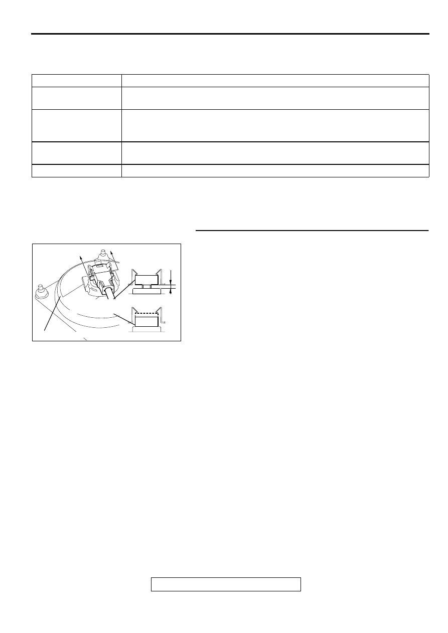
STEP 1. Check the clock spring connector C-81
(1) Remove the air bag module mounting equipment and check
clock spring connector C-81.At this time, check that there is
no gap at place B shown in the illustration. (Refer to
Q: Are connectors correctly connected?
YES : Go to Step 2.
NO : Insert connector to the place, where there remains no
gap at place B shown in the illustration. Then go to
Step 5.
CODE NO.
SYMPTOMS
21
•
Short circuit in driver's side air bag module (squib) or harness
•
Short circuit in clock spring
22
•
Open circuit in driver's side air bag module (squib) or harness
•
Open circuit in clock spring
•
Malfunction of connector contact
61
•
Short circuit in driver's side air bag module (squib) harness leading to the power
supply
62
•
Short circuit in driver's side air bag module (squib) harness leading to the ground
AC002016AD
A
A
B
SECTION A – A
NO GOOD
GOOD
INFLATOR CACE
CLOCK SPRING
CONNECTOR: C-81
SRS AIR BAG DIAGNOSIS
TSB Revision
SUPPLEMENTAL RESTRAINT SYSTEM (SRS)
52B-24
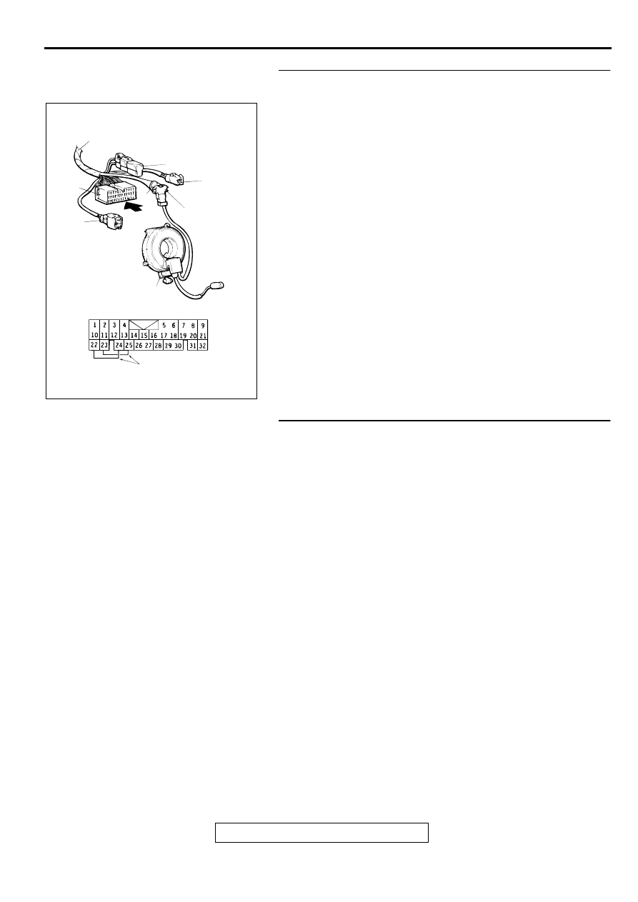
STEP2. Check the driver's side air bag module line using
the scan tool and MB991613 SRS Check harness.
(1) Remove the driver's side air bag module.(Refer to
(2) Connect connector (4) of special tool MB991613 to clock
spring connector C-81.
(3) Connect connector (1) of special tool MB991613 to
connector (2).
(4) Connect terminals 22 to 24, and terminals 23 to 25 of
special tool MB991613 connector (5).
(5) Connect the clock spring to the body wiring harness.
(6) Connect the negative battery terminal.
(7) Erase the DTC memory.
Q: Is any of code number 21, 22, 61 or 62 output?
YES : Go to Step 3.
NO : Replace the driver's side air bag module. Refer to.
Then go to Step 5.
STEP 3. Check the clock spring.
(1) Check the connectors and protective tube for damaged,
and the terminal for deformation.
(2) Visually check the case for damaged.
Q: Is any malfunction found on the clock spring?
YES : Replace the clock spring. Refer to
. Then go
to Step 5.
NO : Go to Step 4.
AC000360
MB991613
RESISTANCE(3
Ω
)
C-81
CLOCK
SPRING
1
4
5
2
A
VIEW A
CONNECT
RESPECTIVELY
AC
SRS AIR BAG DIAGNOSIS
TSB Revision
SUPPLEMENTAL RESTRAINT SYSTEM (SRS)
52B-25
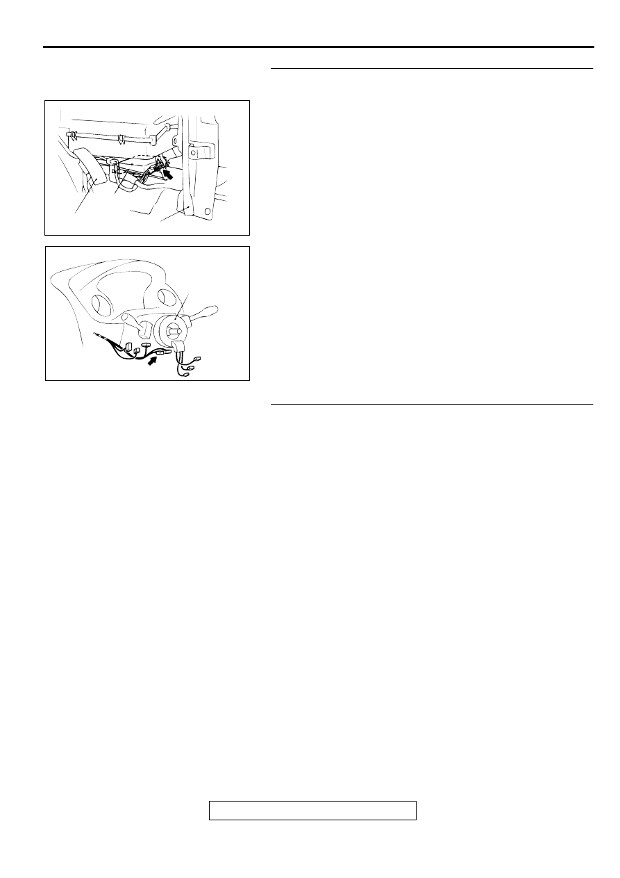
STEP 4. Check the harness wires between SRS-ECU
connector C-72 and clock spring connector C-85.
Q: Are the harness wires between SRS-ECU connector C-
72 and clock spring connector C-85 in good condition?
YES : Go to Step 5.
NO : Repair the harness wires between SRS-ECU
connector C-72 and clock spring connector C-85.
Then go to Step 5.
STEP 5. Check the DTC.
Q: Is any of DTC 21, 22, 61 or 62 output?
YES : Return to Step 1.
NO : This diagnosis is compleate.(If no malfunctions are
not found in all steps, an intermittent malfunction is
suspected. Refer to GROUP 00, How to Use
Troubleshooting/Inspection Service Points
−
How to
Cope with Intermittent Malfunction
.)
AC000358AD
SRS-ECU
ACCELERATOR PEDAL
CENTER REINFORCEMENT(LH)
CONNECTOR: C-72
AC000359AC
CONNECTOR: C-85
CLOCK
SPRING
SRS AIR BAG DIAGNOSIS
TSB Revision
SUPPLEMENTAL RESTRAINT SYSTEM (SRS)
52B-26
DTC 24: Passenger (front) side-air bag module (squib) system fault 1
DTC 25: Passenger (front) side-air bag module (squib) system fault 2
DTC 64: Passenger (front) side-air bag module (squib) system fault for power supply circuit
DTC 65: Passenger (front) side-air bag module (squib) system fault for ground circuit
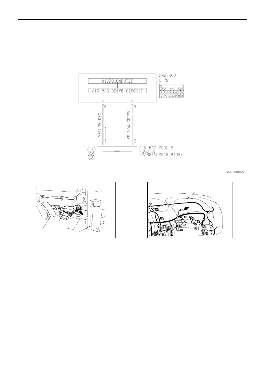
CIRCUIT OPERATION
•
The SRS-ECU judges how severe a collision is
by detecting signals from the left and right side
impact sensors and the analog G-sensor. If the
impact is over a predetermined level, the SRS-
ECU outputs an ignition signal. At this time, if the
safing G-sensor is on, the SRS air bag will inflate.
•
The ignition signal is input to the air bag module
to inflate the air bag.
DTC SET CONDITIONS
•
These DTC are output if there is abnormal
resistance between the input terminals of the
front passenger's side air bag module (squib).
The most likely causes for this code to be set are
shown in the table below: However, if no DTC
resets, the SRS warning light will be switched off
(The DTC will be retained). <Vehicles SRS side
air bag>
TROUBLESHOOTING HINTS
•
Damaged wiring harnesses or connectors
•
Malfunction of the front passenger's side air bag
module (squib)
•
Malfunction of the SRS-ECU
AC003882AB
Front Passenger's Side Air Bag Module (Squib) Circuit
AC000358AD
SRS-ECU
ACCELERATOR PEDAL
CENTER REINFORCEMENT(LH)
CONNECTOR: C-72
AC000363AC
CONNECTOR: C-11
PASSENGER'S SIDE
AIR BAG
Нет комментариевНе стесняйтесь поделиться с нами вашим ценным мнением.
Текст