Mitsubishi Eclipse / Eclipse Spyder (2000-2002). Service and repair manual — part 672
TSB Revision
SUPPLEMENTAL RESTRAINT SYSTEM (SRS)
52B-15
M1524000300079
WARNING
•
In order to avoid injury to yourself or others from
accidental deployment of the air bag during
servicing, read and carefully follow all the
precautions and procedures described in this
manual.
•
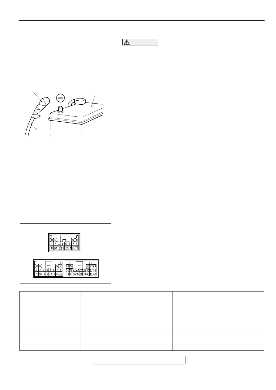
After disconnecting the battery cable, wait 60
seconds or more before proceeding with the
following work. The SRS system is designed to
retain enough voltage to deploy the air bag for a
short time even after the battery has been
disconnected, so serious injury may result from
unintended air bag deployment if work is done on
the SRS system immediately after the battery
cables are disconnected.
•
Battery posts, terminals and related accessories
contain lead and lead compounds. WASH HANDS
AFTER HANDLING.
•
Do not use any electrical test equipment on or near
the SRS components, except those specified on
•
Never Attempt to Repair the Following
Components: SRS-ECU, Clock Spring, Air Bag
Module, Side Impact Sensor. If any of these
components are diagnosed as faulty, they should
only be replaced, in accordance with the
INDIVIDUAL COMPONENT SERVICE procedures in
this manual, starting on page
•
Do not attempt to repair the wiring harness
connectors of the SRS. If any of the connectors are
diagnosed as faulty, replace the wiring harness. If
the wires are diagnosed as faulty, replace or repair
the wiring harness according to the following
table.
ACX00583
INSULATING TAPE
BATTERY
BATTERY CABLE (–)
AC
AC002967AB
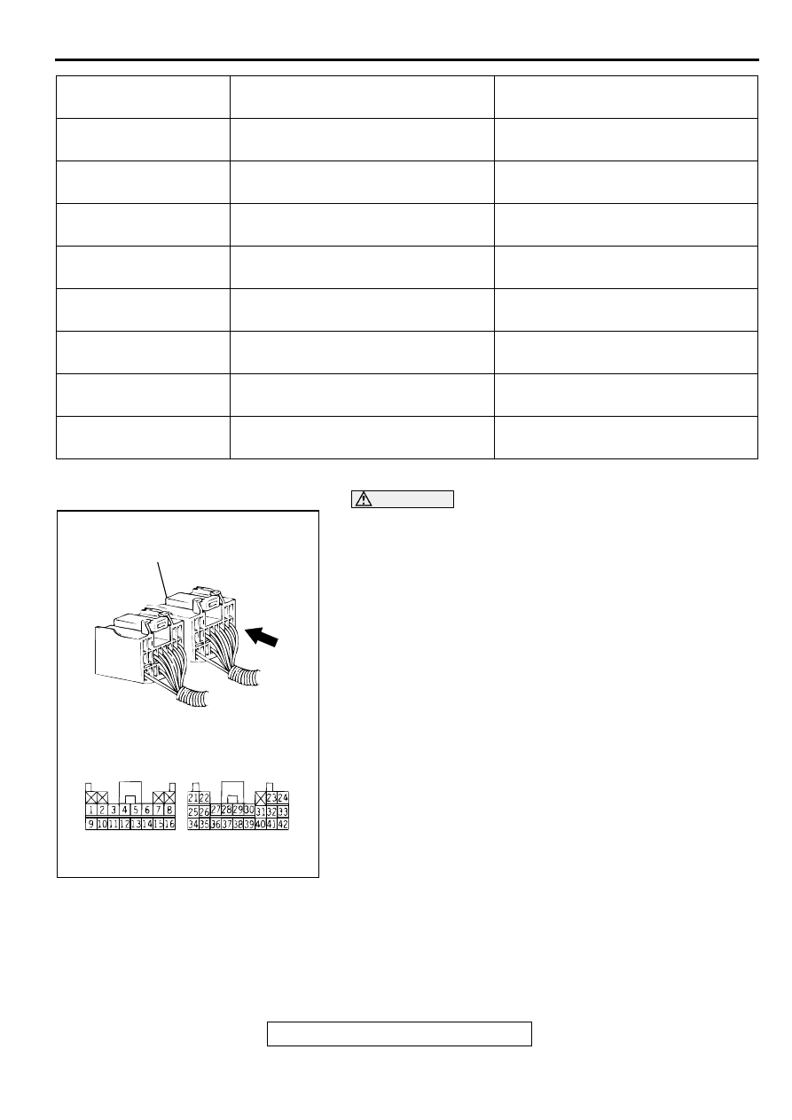
SRS-ECU CONNECTOR
<VEHICLES WITHOUT SRS SIDE AIR BAG>
<VEHICLES WITH SRS SIDE AIR BAG>
SRS-ECU TERMINAL
NO.
DESTINATION OF HARNESS
CORRECTIVE ACTION
3
Body wiring harness
→
Ground
Correct or replace the body wiring
harness.
4
Body wiring harness
→
Instrument
panel wiring
→
SRS warning light
Correct or replace each wiring harness.
5, 6
Body wiring harness
→
Air bag module
(Front passenger's side)
Correct or replace the body wiring
harness.
TSB Revision
SUPPLEMENTAL RESTRAINT SYSTEM (SRS)
52B-16
NOTE: *Vehicles with side air bags
WARNING
•
Inspection of the SRS-ECU connector harness
should be carried out by the following procedure.
Insert the backprobing tool into connector from
harness side, and connect the tester to
backprobing tool. If any tool other than
backprobing tool is used, it may cause damage to
the harness and other components. Furthermore,
measurement should not be carried out by
touching the backprobing tool directly against the
terminals from the front of the connector. The
terminals are plated to increase their conductivity,
so if they are touched directly by the backprobing
tool, the plating may break, which will decrease
reliability.
•
The SRS components should not be subjected to
heat over 93
°
C (200
°
F), so remove the SRS-ECU,
air bag module, and clock spring before drying or
baking the vehicle after painting.
•
After servicing the SRS system, check the warning
light operation to make sure that the system
functions properly. (Refer to
•
Make certain that the ignition switch is "LOCK"
(OFF) position when the scan tool is connected or
disconnected.
•
If you have any questions about the SRS system,
please contact the MMSA Tech Line.
7, 8
Body wiring harness
→
Clock spring
→
Air bag module (Driver's side)
Correct or replace each wiring harness.
Replace the clock spring.
9Body wiring harness
→
Junction block
(fuse No.5)
Correct or replace the body wiring
harness.
12
Body wiring harness
→
Function block
(fuse No.13)
Correct or replace the body wiring
harness.
16
Body wiring harness
→
Data link
connector
Correct or replace the body wiring
harness.
21*, 22*
Body wiring harness
→
Side air bag
module (LH)
Correct or replace the body wiring
harness.
23*, 24*
Body wiring harness
→
Side air bag
module (RH)
Correct or replace the body wiring
harness.
34*, 35*, 36*
Body wiring harness
→
Floor wiring
harness
→
Side impact sensor (LH)
Correct or replace each wiring harness.
40*, 41*, 42*
Body wiring harness
→
Floor wiring
harness
→
Side impact sensor (RH)
Correct or replace each wiring harness.
SRS-ECU TERMINAL
NO.
DESTINATION OF HARNESS
CORRECTIVE ACTION
AC003072
SRS-HARNESS CONNECTOR
SRS-ECU HARNESS CONNECTOR
(REAR SIDE)
AB
SRS AIR BAG DIAGNOSIS
TSB Revision
SUPPLEMENTAL RESTRAINT SYSTEM (SRS)
52B-17
SR S A IR B A G D IA G N O SIS
INTRODUCTION TO DIAGNOSIS
M1524005000073
The SRS system is controlled by the SRS-ECU. The
SRS-ECU judges how severe a collision is by
detecting signals from the analog G-sensor. If the
impact is over a predetermined level, the SRS-ECU
outputs an ignition signal. At this time, if the safing G-
sensor is on, the SRS air bag will inflate. The SRS
warning light in the combination meter alerts a
malfunction of the SRS system. If the following
symptoms occur even when the vehicle has not been
in a collided, there may be a malfunction in the SRS
system.
•
The SRS warning light does not go off within
approximately 7 seconds after the ignition switch
has been turned "ON".
•
The SRS warning light does not illuminate when
the ignition switch is turned "ON".
Refer to the Post-collision Diagnosis when inspecting
and servicing the vehicle that has been in a collision
(Refer to
.).
TROUBLESHOOTING STRATEGY
M1524003100074
Use these steps to plan your diagnostic strategy. If
you follow them carefully, you will be sure that you
have exhausted all of the possible ways to find a
SRS fault.
1. Gather information about the problem from the
customer.
2. Verify that the condition described by the
customer exists.
3. Check the vehicle for any SRS DTC.
4. If you cannot verify the condition but there are no
SRS DTCs, the malfunction is intermittent. Refer
to GROUP 00, How to use Troubleshooting
−
Inspection Service Points
−
How to Cope with
Intermittent Malfunctions
5. If there is a SRS DTC, record the code number,
then erase the code from vehicle memory using
scan tool MB991502.
6. Recreate the SRS DTC set conditions to see if the
same SRS DTC will set again.
•
If the same SRS DTC sets again, follow the
Inspection Chart for DTC and find the fault.
•
If you cannot get the same SRS DTC to set
again, the malfunction is intermittent. Refer to
GROUP 00, How to use Troubleshooting
−
Inspection Service Points
−
How to Cope with
Intermittent Malfunctions
SRS DTC DIAGNOSIS
M1524003200071
Required Special Tool:
•
MB991502: Scan Tool (MUT-II)
CAUTION
To prevent damage to scan tool MB991502, always turn the
ignition switch to "LOCK" (OFF) position before
connecting or disconnecting scan tool MB991502.
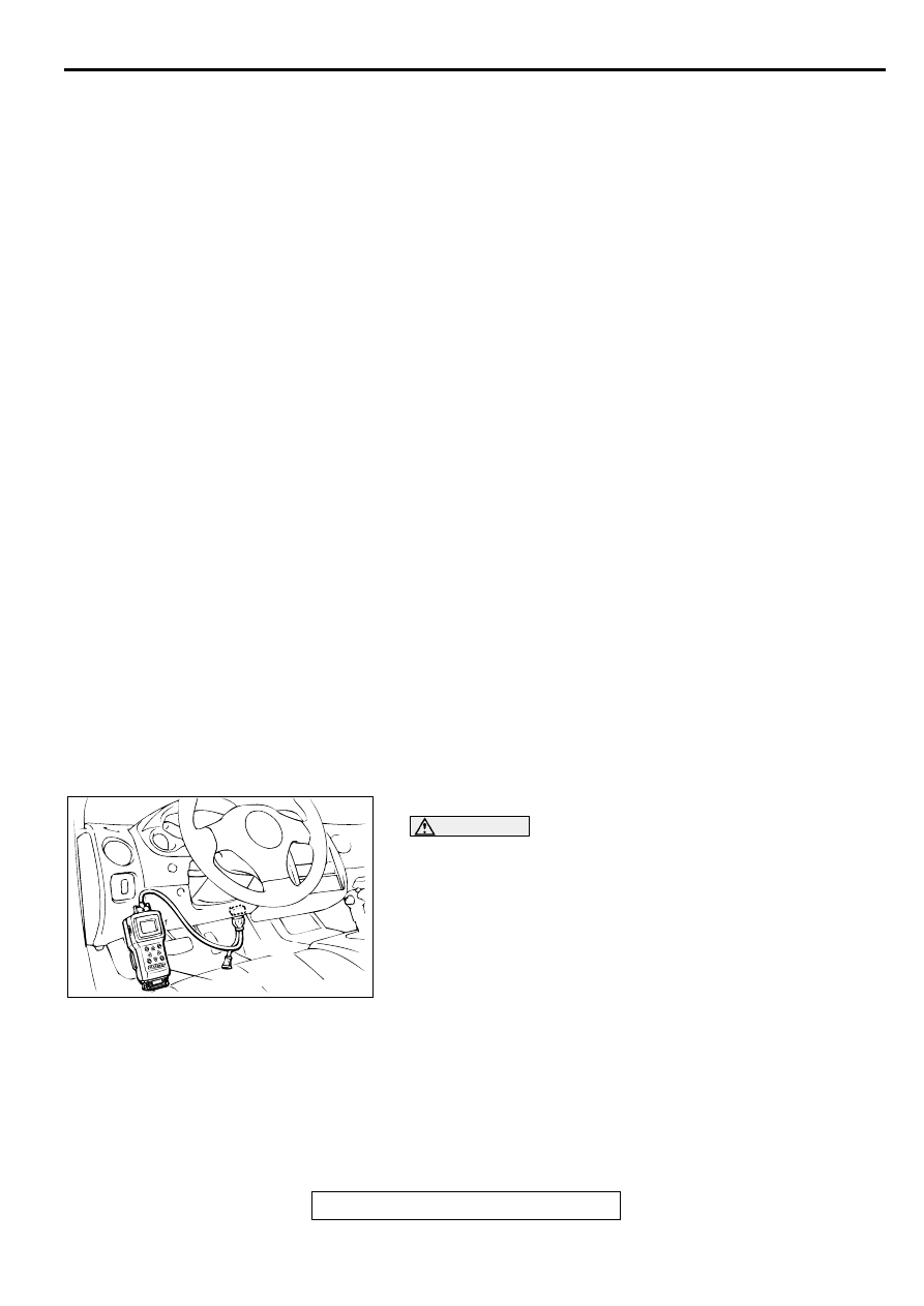
RETRIEVING SRS DTC
Connect scan tool MB991502 to the data link connector, and
then check DTC.
ERASING SRS DTC
Connect scan tool MB991502 to the data link connector, and
then erase the DTC.
AC000356AB
16PIN
MB991502

SRS AIR BAG DIAGNOSIS
TSB Revision
SUPPLEMENTAL RESTRAINT SYSTEM (SRS)
52B-18
DTC CHART
M1524003300119
Inspect according to the inspection chart that is appropriate for the DTC.
CODE NO.
ON-BOARD DIAGNOSTIC ITEM
REFERENCE PAGE
14
Analog G-sensor system in the SRS-ECU
15
Safing G-sensor short circuit
16
Safing G-sensor open circuit
17
Safing G-sensor for side air bag faults
21*
2
Driver's side air bag module (squib) system fault 1
22*
2
Driver's side air bag module (squib) system fault 2
24*
2
Front passenger's side air bag module (squib) system fault 1
25*
2
Front passenger's side air bag module (squib) system fault 2
31
SRS-ECU capacitor circuit voltage too high
32
SRS-ECU capacitor circuit voltage too low
34*
1
Connector lock system detects connector unlocked
35
SRS-ECU air bag condition monitor detects deployed air bag
41*
1
IG1 power circuit system (fuse No.13 circuit)
42*
1
IG1 power circuit system (fuse No.5 circuit)
43
SRS warning light drive circuit
system fault 1
Light does not illuminate*
1
Light does not switch off
44*
1
SRS warning light drive circuit system fault 2
45
SRS-ECU non-volatile memory (EEPROM) and A/D
converter system
51
Driver's side air bag module (squib ignition drive circuit)
system detected short circuit
52
Driver's side air bag module (squib ignition drive circuit) system
detected open circuit
54
Front passenger's side air bag module (squib ignition drive circuit)
system detected short circuit
55
Passenger (front)-side air bag module (squib ignition drive circuit)
system detected short circuit
61
Driver's side air bag module (squib) system fault for power supply
circuit
62
Driver's side air bag module (squib) system fault for ground circuit
64
Passenger (front) side-air bag module (squib) system fault for
power supply circuit
65
Passenger (front) side-air bag module (squib) system fault for
ground circuit
71*
2
Right hand side-air bag module (squib) system fault 1
72*
2
Right hand side-air bag module (squib) system fault 2
Нет комментариевНе стесняйтесь поделиться с нами вашим ценным мнением.
Текст