Mitsubishi Eclipse / Eclipse Spyder (2000-2002). Service and repair manual — part 686
AIR BAG MODULE(S) AND CLOCK SPRING
TSB Revision
SUPPLEMENTAL RESTRAINT SYSTEM (SRS)
52B-71
Required Special Tools:
•
MB990502: Scan Tool (MUT-II)
•
MB990803: Steering Wheel Puller
•
MB991613: SRS Check Harness
REMOVAL SERVICE POINT
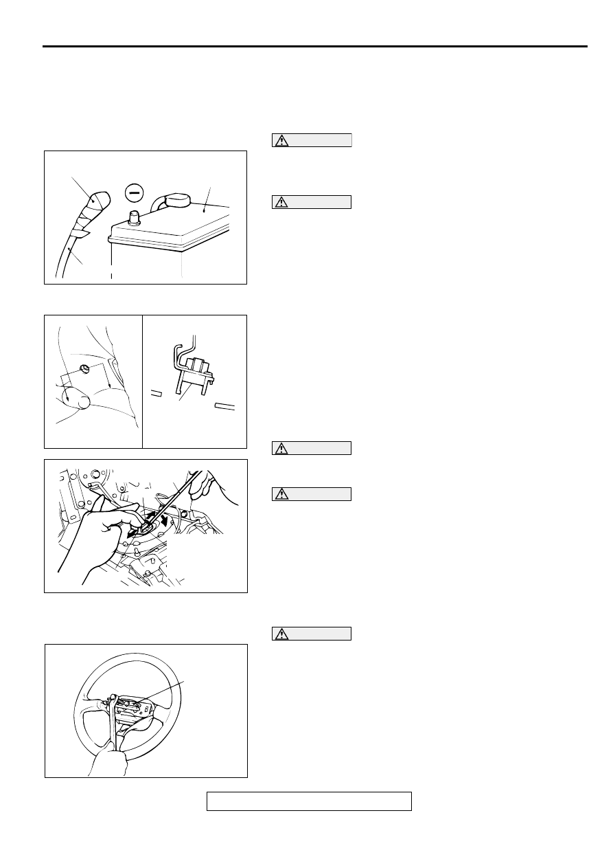
<<A>> NEGATIVE (-) BATTERY CABLE DISCONNECTION
DANGER
Wait at least 60 seconds after disconnecting the
battery cable before doing any further work. (Refer to
.)
WARNING
Battery posts, terminals and related accessories
contain lead and lead compounds. WASH HANDS
AFTER HANDLING.
Disconnect the negative (-) battery cable from the battery and
tape the terminal to prevent accidental connection and air
bag(s) deployment.
<<B>> AIR BAG MODULE REMOVAL (DRIVER'S SIDE)
1. Remove the air bag module mounting screws (TORX
screws) at the sides of the steering wheel.
NOTE: Do not remove the screws from the holders.
WARNING
The removed air bag module should be stored in a
clean, dry place with the pad cover face up.
CAUTION
When disconnecting the air bag module-to-clock spring
connector, take care not to apply excessive force to it.
2. When disconnecting the connector of the clock spring from
the air bag module, press the air bag's lock toward the outer
side to spread to open. Use a flat-tipped screwdriver, as
shown in the figure at the left, to pry gently to remove the
connector.
<<C>> STEERING WHEEL REMOVAL
CAUTION
Do not hammer on the steering wheel. Doing so may
damage the collapsible column mechanism.
ACX00583
INSULATING TAPE
BATTERY
BATTERY CABLE (–)
AC
AC000395AB
SECTION A – A
A
A
MOUNTING
SCREW
(TORX®
SCREW)
AC000396AB
FLAT-TIPPED
SCREWDRIVER
LOCK
CLOCK
SPRING-TO-AIR
BAG MODULE
CONNECTOR
LOCK
AC000397AB
MB990803
AIR BAG MODULE(S) AND CLOCK SPRING
TSB Revision
SUPPLEMENTAL RESTRAINT SYSTEM (SRS)
52B-72
<<D>> CLOCK SPRING REMOVAL
WARNING
The removed clock spring should be stored in a
clean, dry place.
<<E>> AIR BAG MODULE REMOVAL (FRONT
PASSENGER'S SIDE)
WARNING
The removed air bag module should be stored in a
clean, dry place with the pad cover face up.
INSTALLATION SERVICE POINTS
>>A<< PRE-INSTALLATION INSPECTION
WARNING
Dispose of air bag modules only according to the
specified procedure. (Refer to
.)
1. When installing the new air bag modules and clock spring,
refer to "INSPECTION (
)."
2. Connect the negative (-) battery cable.
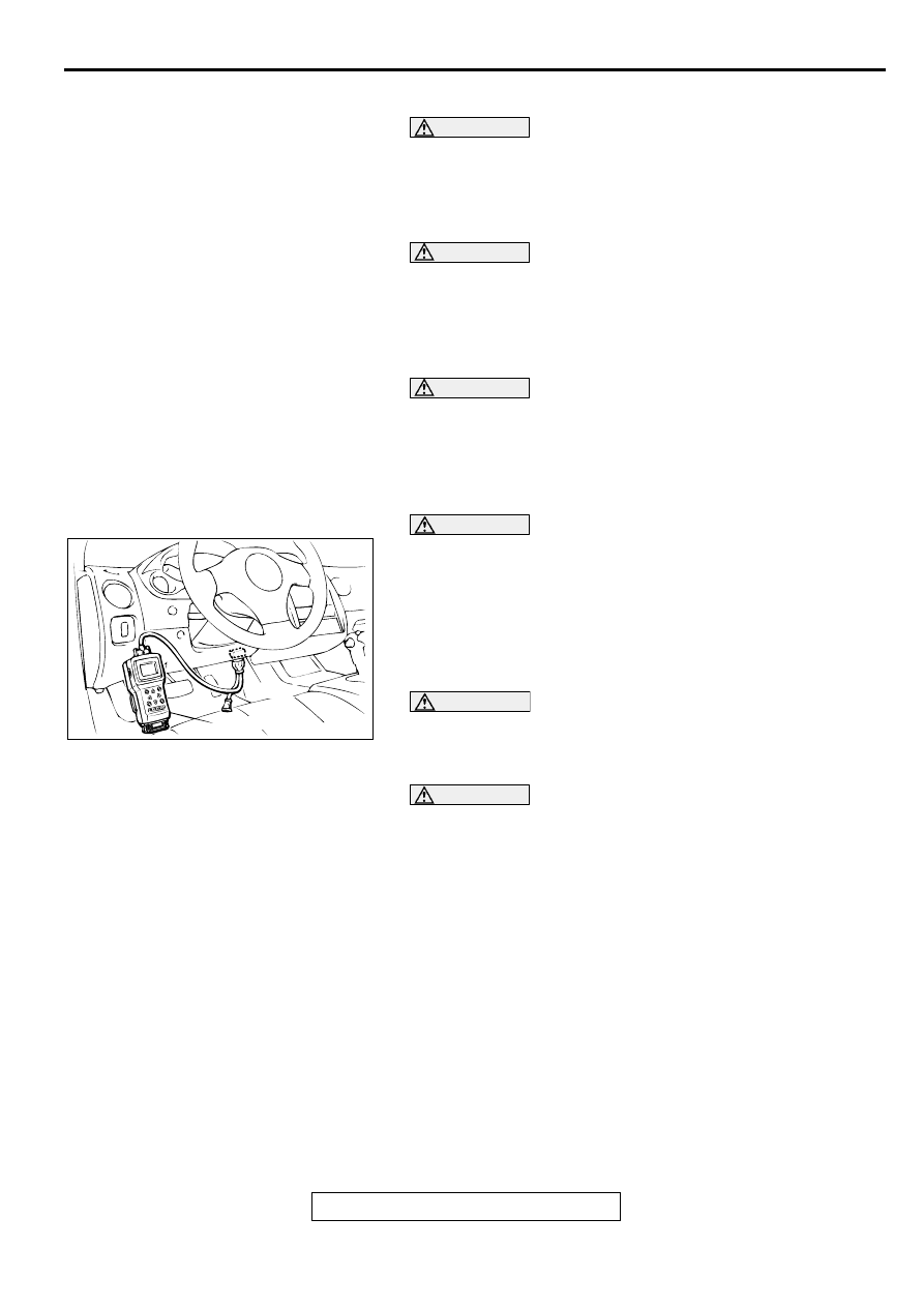
CAUTION
To prevent damage to scan tool MB991502, always turn the
ignition, switch to "LOCK" (OFF) position before
connecting or disconnecting scan tool MB991502.
3. Connect scan tool MB991502 to the data link connector.
4. Turn the ignition switch to "ON" position.
5. Conduct diagnostic test using scan tool MB991502 to
ensure entire SRS operates properly.
DANGER
Wait at least 60 seconds after disconnecting the
battery cable before doing any further work. (Refer to
.)
WARNING
Battery posts, terminals and related accessories
contain lead and lead compounds. WASH HANDS
AFTER HANDLING.
6. Turn the ignition switch to "LOCK" (OFF) position.
Disconnect the negative (-) battery cable and tape the
terminal to prevent accidental connection and air bags
deployment.
AC000356AB
16PIN
MB991502
AIR BAG MODULE(S) AND CLOCK SPRING
TSB Revision
SUPPLEMENTAL RESTRAINT SYSTEM (SRS)
52B-73
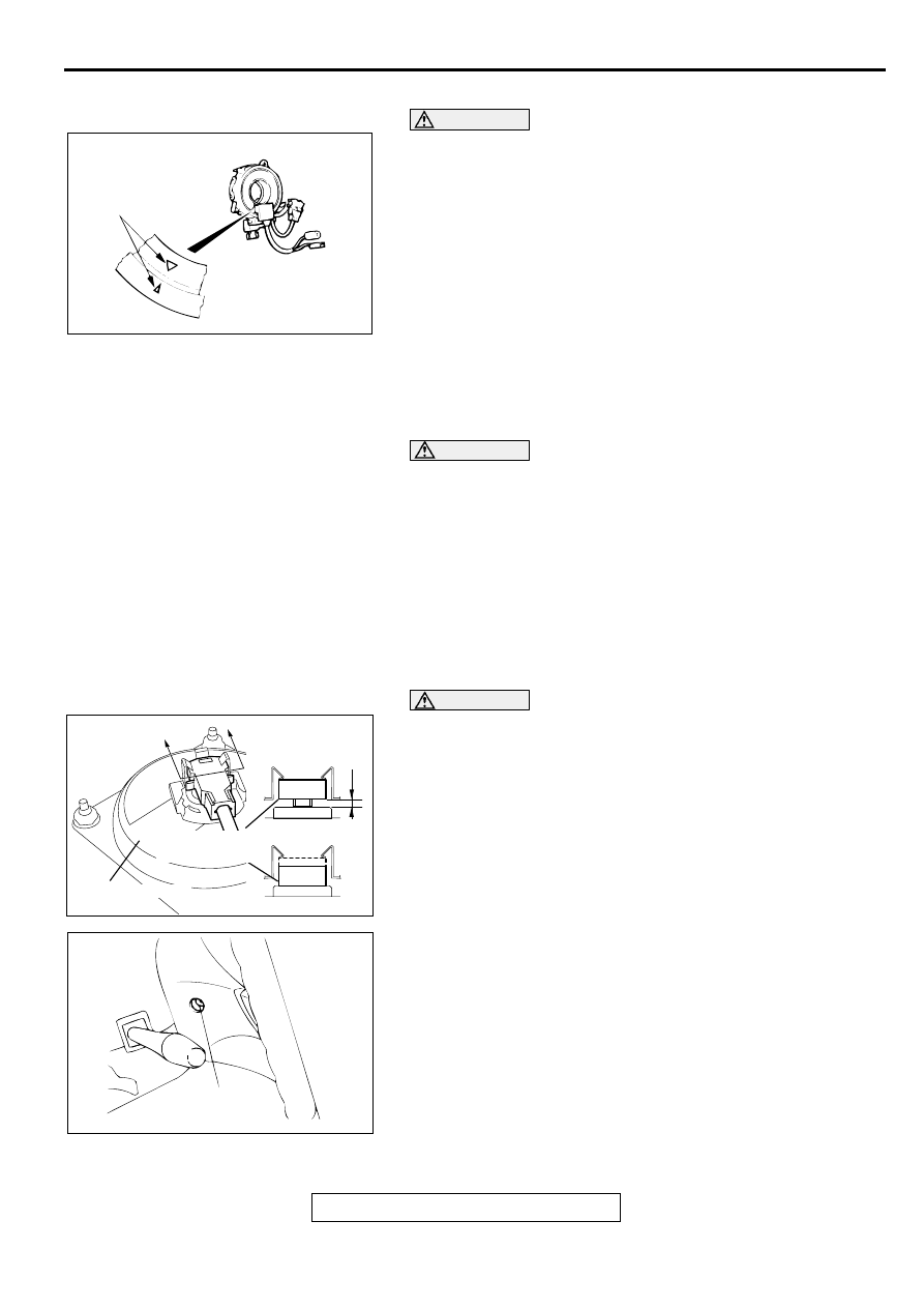
>>B<< CLOCK SPRING INSTALLATION
WARNING
Ensure that the clock spring's mating marks are
properly aligned. If not, the steering wheel may not
rotate completely during a turn, or the flat cable in the
clock spring could be damaged. This would prevent
normal SRS operation and possibly cause serious
injury to the driver.
Align the mating marks of the clock spring. Turn the front
wheels to the straight-ahead position. Then install the clock
spring to the column switch.
<Mating Mark Alignment>
Turn the clock spring clockwise fully. Then turn it back
approximately 3 turns counterclockwise to align the mating
marks.
>>C<< STEERING WHEEL INSTALLATION
CAUTION
When installing the steering wheel, ensure that the
harness of the clock spring does not become caught or
tangled.
1. Before installing the steering wheel, turn the vehicle's front
wheels to the straight-ahead position and align the mating
marks of the clock spring.
2. After securing the steering wheel, turn the steering wheel all
the way in both directions to confirm that the steering wheel
rotation is normal.
>>D<< AIR BAG MODULE INSTALLATION (DRIVER'S SIDE)
CAUTION
If there is gap at place B shown in the illustration, that
means the connector is not firmly inserted, i.e. not
correctly connected. In such a case, insert connector to
the place, where there remains no gap at place B shown in
the illustration.
1. Connect the clock spring connector securely.
2. Tighten the air bag module mounting screws to 9.0
±
2.0
N
⋅
m (78
±
17 in-lb)
AC000398AB
MATING MARKS
AC002016AB
A
INFLATOR CASE
A
SECTION A – A
NO GOOD
GOOD
CLOCK SPRING
CONNECTOR
B
AC000399AB
9.0 ± 2.0 N·m
78 ± 17 in-lb
AIR BAG MODULE(S) AND CLOCK SPRING
TSB Revision
SUPPLEMENTAL RESTRAINT SYSTEM (SRS)
52B-74
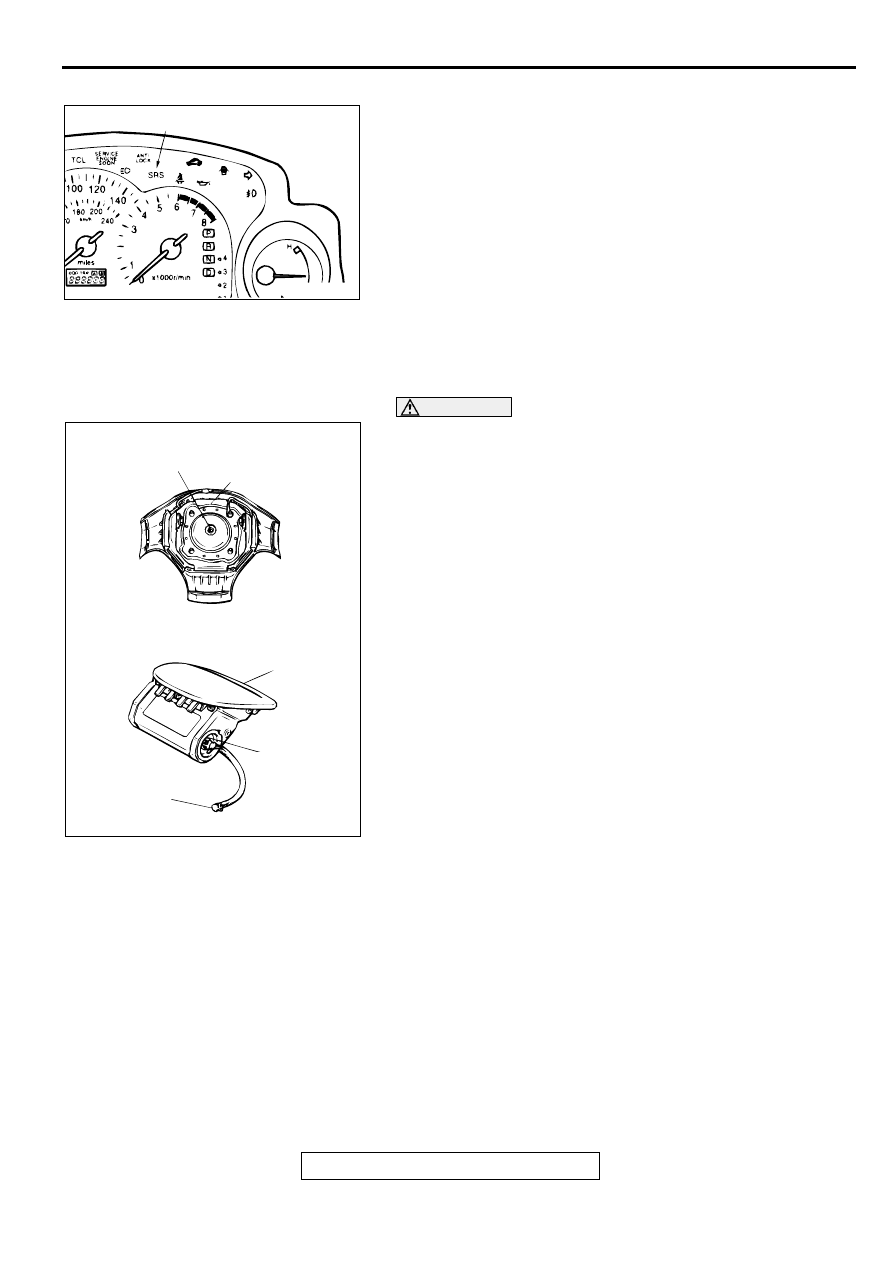
>>E<< POST-INSTALLATION INSPECTION
1. Reconnect the negative (-) battery cable.
2. Turn the ignition switch to "ON" position.
3. Does the "SRS" warning light illuminate for approximately 7
seconds, and then remain off for at least 5 seconds after
turning "OFF"?.
4. If yes, the SRS system is functioning properly. If no, refer to
.
INSPECTION
M1524002500079
AIR BAG MODULE CHECK
WARNING
•
If any component damage is found during the
following inspection, replace the air bag module
with a new one. Dispose of the old one according
to the specified procedure. (Refer to
.)
•
Never attempt to measure the circuit resistance of
the air bag modules (squib) even if you are using
the specified tester. If the circuit resistance is
measured with a tester, accidental air bag
deployment will result in serious personal injury.
1. Check the pad cover for dents, cracks or deformation.
2. Check the connectors for damage, the terminals for
deformation, and the harness for binds.
3. Check the air bag inflator vase for dents, cracks or
deformation.
4. Install the air bag module (driver's side) to the steering
wheel and check fit and alignment with the wheel.
5. Install the air bag module (front passenger's side) to the
instrument panel and crossmember and check fit and
alignment.
6. Install the air bag module cover (front passenger's side) to
the instrument panel to check fit and alignment.
AC000346AB
SRS WARNING LIGHT
AC000388AB
CONNECTOR
<DRIVER'S SIDE>
<FRONT PASSENGER'S SIDE>
INFLATOR CASE
CONNECTOR
INFLATOR CASE
COVER
Нет комментариевНе стесняйтесь поделиться с нами вашим ценным мнением.
Текст