Mitsubishi Eclipse / Eclipse Spyder (2000-2002). Service and repair manual — part 684

POST-COLLISION DIAGNOSIS
TSB Revision
SUPPLEMENTAL RESTRAINT SYSTEM (SRS)
52B-63
Data list
4. Erase the DTC and, after waiting 5 seconds or more, read
(and write down) all displayed DTC. (Refer to
REPAIR PROCEDURE
WHEN FRONT AIR BAGS DEPLOY IN A COLLISION.
1. Replace the following parts with new ones.
•
SRS-ECU (Refer to
•
Air bag module (Refer to
2. Check the following parts and replace if there are any
malfunctions.
•
Clock spring (Refer to
•
Steering wheel, steering column and intermediate joint
(1) Check the wiring harness (built into the steering wheel)
and connectors for damage, and terminals for
deformation.
(2) Install the air bag module to check fit or alignment with
the steering wheel.
(3) Check the steering wheel for noise, binds or difficult
operation and excessive free play.
3. Check the wiring harnesses for binding, the connectors for
damage, poor connections, and the terminals for
deformation. (Refer to
WHEN SIDE AIR BAG DEPLOYS IN A COLLISION.
1. Replace the following parts with new ones.
•
SRS-ECU (Refer to
•
.)
•
Front seat back assembly (Refer to GROUP 52A, Front
seat
.)
2. Check the wiring harnesses for binding, the connectors for
damage, poor connections, and the terminals for
deformation. (Refer to
NO.
SERVICE DATA ITEM
APPLICABILITY
92
Number indicating how often the memory is
cleared
Maximum time to be stored: 250
93
How long a problem has lasted (How long it
takes from the occurrence of the problem till
the first air bag squib igniting signal)
Maximum time to be stored: 9,999 minutes
(approximately 7 days)
94
How long a problem has lasted (How long it
takes from the first air bag squib igniting
signal till now.)
POST-COLLISION DIAGNOSIS
TSB Revision
SUPPLEMENTAL RESTRAINT SYSTEM (SRS)
52B-64
WHEN AIR BAG DOES NOT DEPLOY IN LOW-SPEED
COLLISION.
Check the SRS components. If the SRS components are
showing any visible damage such as dents, cracks, or
deformation, replace them with new ones. Concerning parts
removed for inspection, replacement with new parts and
cautionary points for working, refer to appropriate INDIVIDUAL
COMPONENT SERVICE,
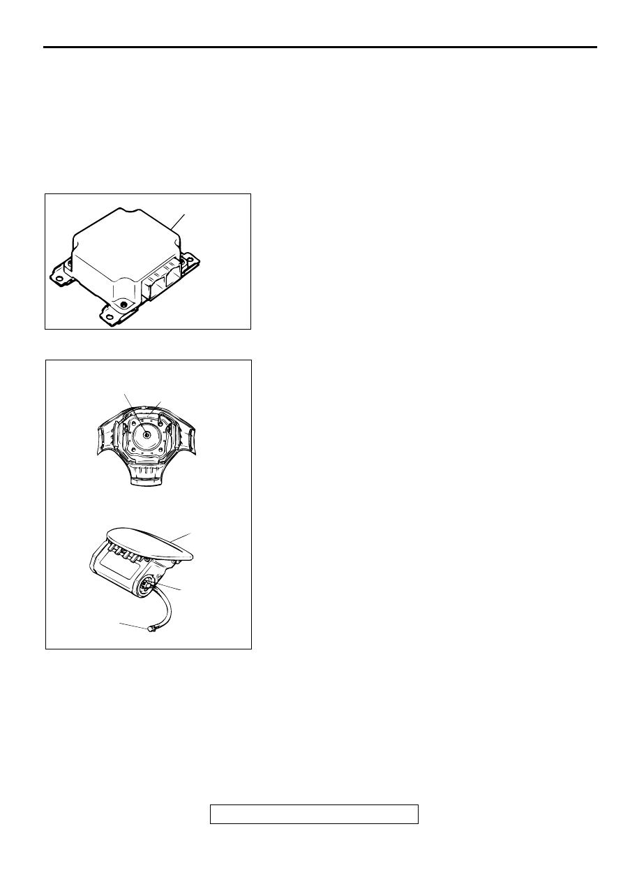
SRS-ECU
1. Check the SRS-ECU case and brackets for dents, cracks or
deformation.
2. Check the connector for damage, and the terminals for
deformation.
Air bag modules
1. Check the pad cover for dents, cracks or deformation.
2. Check the connector for damage, terminals deformities, and
the harness for binding.
3. Check the air bag inflator case for dents, cracks or
deformities.
4. Install the air bag module (driver's side) to the steering
wheel to check fit or alignment with the steering wheel.
5. Install the air bag module (front passenger's side) to the
instrument panel and crossmember to check fit or alignment.
6. Install the air bag module cover (front passenger's side) to
the instrument panel to check fit or alignment.
AC003132AB
SRS-ECU
AC000388AB
CONNECTOR
<DRIVER'S SIDE>
<FRONT PASSENGER'S SIDE>
INFLATOR CASE
CONNECTOR
INFLATOR CASE
COVER
POST-COLLISION DIAGNOSIS
TSB Revision
SUPPLEMENTAL RESTRAINT SYSTEM (SRS)
52B-65
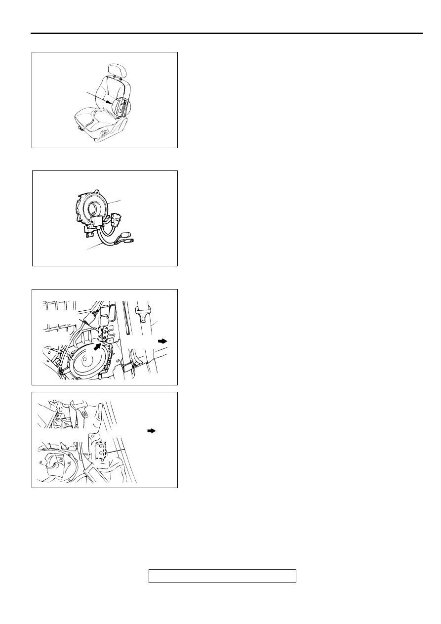
Front seat back assembly (Side air bag module)
1. Check that there is no abnormality in the seat air bag
module deployment section.
2. Check that there is no connector damage, bent terminals or
clamping of the harness.
Clock spring
1. Check the clock spring connectors and protective tube for
damage, and the terminals for deformation.
2. Visually check the case for damage.
Side impact sensor
1. Check that there is no bending or corrosion in the center
pillar.
2. Check that there is no denting, breakage or bending of the
side impact sensor.
3. Check that there is no clamping of the harness, connector
damage or bent terminals.
NOTE: The illustration at left shows the side impact sensor
(LH). The position of the side impact sensor (RH) is
symmetrical to this.
AC002988AB
AIR BAG MODULE
DEPLOYMENT
SECTION
AC000390AB
CASE
PROTECTIVE TUBE
AC002979AC
<ECLIPSE>
SIDE IMPACT
SENSOR
REAR
SPEAKER
FRONT OF
VEHICLE
AC003017AB
REAR SPEAKER
BRACKET
SIDE IMPACT
SENSOR
FRONT OF
VEHICLE
<ECLIPSE SPYDER>
INDIVIDUAL COMPONENT SERVICE
TSB Revision
SUPPLEMENTAL RESTRAINT SYSTEM (SRS)
52B-66
Steering wheel, steering column and intermediate joint
1. Check the wiring harness (built into the steering wheel) and
the connectors for damage, and the terminals for
deformation.
2. Install the air bag module to check fit or alignment with the
steering wheel.
3. Check the steering wheel for noise, binding or difficult
operation and excessive free play.
Harness connector (floor wiring harness)
Check the harnesses for binding, the connectors for damage,
poor connection, and the terminals for deformation. (Refer to
IN D IVID U A L C O M PO N ENT SERVIC E
M1524002900077
WARNING
•
The SRS components should not be subjected to heat over 93
°Χ (200°
F), so remove the
SRS-ECU, air bag modules (driver's side and front passenger's side), front seat
assemblies (side air back module), clock spring, side impact sensors before drying or
baking the vehicle after painting. Recheck the SRS system operability after reinstalling
them. (Refer to GROUP 00, Maintenance Service -SRS Maintenance
•
If the SRS components are removed for the purpose of checking, sheet metal repair,
painting, etc., they should be stored in a clean, dry place until they are reinstalled.
If the SRS components are to be removed or replaced as a result of maintenance, diagnosis, etc., follow the
appropriate procedure in this section. (SRS Air Bag Control Unit: refer to
, Air Bag Modules and
Clock Spring: refer to
, Side impact sensor: refer to
SR S C O N TRO L UN IT (SRS-EC U )
M1524002100071
WARNING
•
Never attempt to disassemble or repair the SRS-ECU. If faulty, replace it.
•
Do not drop or subject the SRS-ECU to impact or vibration. If denting, cracking,
deformation, or rust are discovered in the SRS-ECU, replace it with a new SRS-ECU.
Discard the old one.
•
After deployment of an air bag, replace the SRS-ECU with a new one.
•
Never use an ohmmeter on or near the SRS-ECU, and use only the special test equipment
described on
.
Нет комментариевНе стесняйтесь поделиться с нами вашим ценным мнением.
Текст