Mitsubishi Eclipse / Eclipse Spyder (2000-2002). Service and repair manual — part 254
MULTIPORT FUEL INJECTION (MFI) DIAGNOSIS
TSB Revision
MULTIPORT FUEL INJECTION (MFI) <3.0L ENGINE>
13B-215
STEP 14. Test the OBD-II drive cycle.
(1) Carry out a test drive with the drive cycle pattern. Refer to,
Procedure 2
−
Fuel Trim Monitor (
(2) Check the diagnostic trouble code (DTC).
Q: Is the DTC P0174 is output?
YES : Retry the troubleshooting.
NO : The inspection is complete.
DTC P0175: System too Rich (bank 2)
System too Rich (bank 2) Circuit
•
Refer to, DTC P0202, P0204, P0206
−
Injector
Circuit (
CIRCUIT OPERATION
•
Refer to, DTC P0202, P0204, P0206
−
Injector
Circuit (
TECHNICAL DESCRIPTION
•
If a malfunction occurs in the fuel system, the fuel
trim value becomes too small.
•
The ECM <M/T> or PCM <A/T> checks whether
the fuel trim value is within a specified range.
DTC SET CONDITIONS
Check Area
•
Engine coolant temperature is lower than
approximately 100
°
C (212
°
F) when the engine
is started.
•
Intake air temperature is lower than 60
°
C (140
°
F) when the engine is started.
•
Under the closed loop air/fuel ratio control.
•
Intake air temperature is higher than -10
°
C (14
°
F).
•
Barometric pressure is higher than 76kPa (11
psi).
•
Volume air flow sensor output frequency is 75 Hz
or more.
Judgment Criteria
•
Long-term fuel trim has continued to be lower
than -12.5 for 5 seconds.
or
•
Short-term fuel trim has continued to be lower
than -7.4 for 5 seconds.
Check Area
•
Engine coolant temperature is lower than
approximately 100
°
C (212
°
F) when the engine
is started.
•
Intake air temperature is lower than 60
°
C (140
°
F) when the engine is started.
•
Under the closed loop air/fuel ratio control.
•
Intake air temperature is higher than -10
°
C (14
°
F).
•
Barometric pressure is higher than 76kPa (11
psi).
•
Volume air flow sensor output frequency is 75 Hz
or less.
Judgment Criteria
•
Long-term fuel trim has continued to be lower
than -12.5 for 5 seconds.
or
•
Short-term fuel trim has continued to be lower
than -12.4 for 5 seconds.
Check Area
•
Engine coolant temperature is higher than
approximately 100
°
C (212
°
F) when the engine
is started.
•
Intake air temperature is higher than 60
°
C (140
°
F) when the engine is started.
•
Under the closed loop air/fuel ratio control.
•
Intake air temperature is higher than -10
°
C (14
°
F).
•
Barometric pressure is higher than 76kPa (11
psi).
•
Volume air flow sensor output frequency is 75 Hz
or more.
Judgment Criteria
•
Long-term fuel trim has continued to be lower
than -12.5 for 5 seconds.
or
•
Short-term fuel trim has continued to be lower
than -7.4 for 5 seconds.
Check Area
•
Engine coolant temperature is higher than
approximately 100
°
C (212
°
F) when the engine
is started.
•
Intake air temperature is higher than 60
°
C (140
°
F) when the engine is started.
•
Under the closed loop air/fuel ratio control.
MULTIPORT FUEL INJECTION (MFI) DIAGNOSIS
TSB Revision
MULTIPORT FUEL INJECTION (MFI) <3.0L ENGINE>
13B-216
•
Intake air temperature is higher than -10
°
C (14
°
F).
•
Barometric pressure is higher than 76kPa (11
psi).
•
Volume air flow sensor output frequency is 75 Hz
or less.
Judgment Criteria
•
Long-term fuel trim has continued to be lower
than -12.5 for 5 seconds.
or
•
Short-term fuel trim has continued to be lower
than -12.4 for 5 seconds.
Check Area
•
Under the closed loop air/fuel ratio control.
•
The left bank heated oxygen sensor (front) is
active.
Judgment Criteria
•
Long-term fuel trim has continued to be lower
than -12.5 for 5 seconds.
or
•
Short-term fuel trim has continued to be lower
than -30.0 for 5 seconds.
TROUBLESHOOTING HINTS (The most likely
causes for this code to be set are:)
•
Volume air flow sensor failed.
•
Injector (Number 2, 4, 6) failed.
•
Incorrect fuel pressure
•
Left bank heated oxygen sensor failed.
•
Engine coolant temperature sensor failed.
•
Intake air temperature sensor failed.
•
Barometric pressure sensor failed.
•
Exhaust leak.
•
Use of incorrect or contaminated fuel.
•
ECM failed. <M/T>
•
PCM failed. <A/T>
DIAGNOSIS
Required Special Tools
MB991502: Scan Tool (MUT-II)
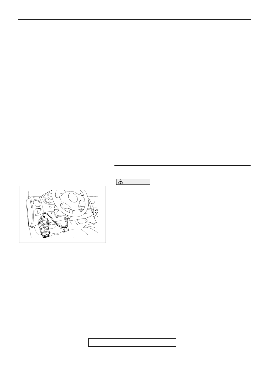
STEP 1. Using scan tool MB991502, check data list item 12:
Volume Air Flow Sensor.
CAUTION
To prevent damage to scan tool MB991502, always turn the
ignition switch to the "LOCK" (OFF) position before
connecting or disconnecting scan tool MB991502.
(1) Connect scan tool MB991502 to the data link connector.
(2) Start the engine and run at idle.
(3) Set scan tool MB991502 to the data reading mode for item
12, Volume Air Flow Sensor.
(4) Warm up the engine to normal operating temperature: 80
°
C to 96
°
C (176
°
F to 205
°
F).
•
When idling, between 17 and 46 Hz (between 2.2 and
5.7 g/s).
•
When 2,500 r/min, between 63 and 103 Hz (between
9.0 and 14.7 g/s).
(5) Turn the ignition switch to the "LOCK" (OFF) position.
Q: Is the sensor operating properly?
YES : Go to Step 2.
NO : Refer to, DTC P0101
−
Volume Air Flow Circuit
Range/Performance Problem (
), DTC P0102
−
Volume Air Flow Circuit Low Input (
), DTC
P0103 - Volume Air Flow Circuit High Input (
AKX01177
16 PIN
MB991502
AB
MULTIPORT FUEL INJECTION (MFI) DIAGNOSIS
TSB Revision
MULTIPORT FUEL INJECTION (MFI) <3.0L ENGINE>
13B-217
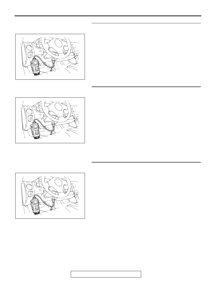
STEP 2. Using scan tool MB991502, check data list item 13:
Intake Air Temperature Sensor.
(1) Turn the ignition switch to the "ON" position.
(2) Set scan tool MB991502 to the data reading mode for item
13, Intake Air Temperature Sensor.
•
The intake air temperature and temperature shown with
the scan tool should approximately match.
(3) Turn the ignition switch to the "LOCK" (OFF) position.
Q: Is the sensor operating properly?
YES : Go to Step 3.
NO : Refer to, DTC P0111
−
Intake Air Temperature Circuit
Range/Performance Problem (
STEP 3. Using scan tool MB991502, check data list item 21:
Engine Coolant Temperature Sensor.
(1) Turn the ignition switch to the "ON" position.
(2) Set scan tool MB991502 to the data reading mode for item
21, Engine Coolant Temperature Sensor.
•
The engine coolant temperature and temperature
shown with the scan tool should approximately match.
(3) Turn the ignition switch to the "LOCK" (OFF) position.
Q: Is the sensor operating properly?
YES : Go to Step 4.
NO : Refer to, DTC P0115
−
Engine Coolant Temperature
Circuit High Input (
), DTC P0116
−
Engine
Coolant Temperature Circuit Range/Performance
Problem (
), DTC P0117
−
Engine Coolant
Temperature Circuit Low Input (
STEP 4. Using scan tool MB991502, check data list item 25:
Barometric Pressure Sensor.
(1) Turn the ignition switch to the "ON" position.
(2) Set scan tool MB991502 to the data reading mode for item
25, Barometric Pressure Sensor.
•
When altitude is 0 m(0 foot), 101 kPa.
•
When altitude is 600 m(1,969 feet), 95 kPa.
•
When altitude is 1,200 m(3,937 feet), 88 kPa.
•
When altitude is 1,800 m(5,906 feet), 81 kPa.
(3) Turn the ignition switch to the "LOCK" (OFF) position.
Q: Is the sensor operating properly?
YES : Go to Step 5.
NO : Refer to, DTC P0107
−
Barometric Pressure Circuit
Low Input (
), DTC P0108
−
Barometric
Pressure Circuit High Input (
AKX01177
16 PIN
MB991502
AB
AKX01177
16 PIN
MB991502
AB
AKX01177
16 PIN
MB991502
AB
MULTIPORT FUEL INJECTION (MFI) DIAGNOSIS
TSB Revision
MULTIPORT FUEL INJECTION (MFI) <3.0L ENGINE>
13B-218
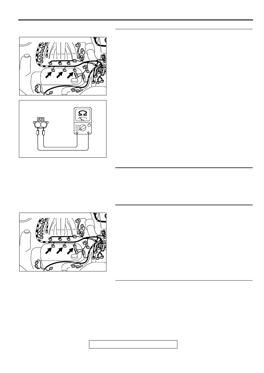
STEP 5. Check the left bank injector.
(1) Disconnect the left bank injector connector B-02, B-06, B-
25.
(2) Measure the resistance between each injector side
connector terminal 1 and 2.
Standard value: 13
−
16 ohm [at 20
°
C (68
°
F)]
Q: Is the resistance standard value?
YES : Go to Step 6.
NO : Replace the faulty injector. Then go to Step 8.
STEP 6. Check the fuel pressure.
Refer to, Fuel Pressure Test (
Q: Is the fuel pressure normal?
YES : Go to Step 7.
NO : Repair or replace it. Then go to Step 8.
STEP 7. Replace the left bank injector.
(1) Replace the left bank injector.
(2) Carry out a test drive with the drive cycle pattern. Refer to,
Procedure 2
−
Fuel Trim Monitor (
(3) Check the diagnostic trouble code (DTC).
Q: Is the DTC P0175 is output?
YES : Replace the ECM or PCM. Then go to Step 8.
NO : The inspection is complete.
STEP 8. Test the OBD-II drive cycle.
(1) Carry out a test drive with the drive cycle pattern. Refer to,
Procedure 2
−
Fuel Trim Monitor (
(2) Check the diagnostic trouble code (DTC).
Q: Is the DTC P0175 is output?
YES : Retry the troubleshooting.
NO : The inspection is complete.
AK000213AB
CONNECTORS : B-02, B-06, B-25
B-02 B-06 B-25
AK000559
2
1
INJECTOR SIDE
CONNECTOR
AB
AK000213AB
CONNECTORS : B-02, B-06, B-25
B-02 B-06 B-25
Нет комментариевНе стесняйтесь поделиться с нами вашим ценным мнением.
Текст