Mitsubishi Eclipse / Eclipse Spyder (2000-2002). Service and repair manual — part 341
THROTTLE BODY ASSEMBLY
TSB Revision
MULTIPORT FUEL INJECTION (MFI) <3.0L ENGINE>
13B-563
TH R O TTLE B O D Y A SSEM B LY
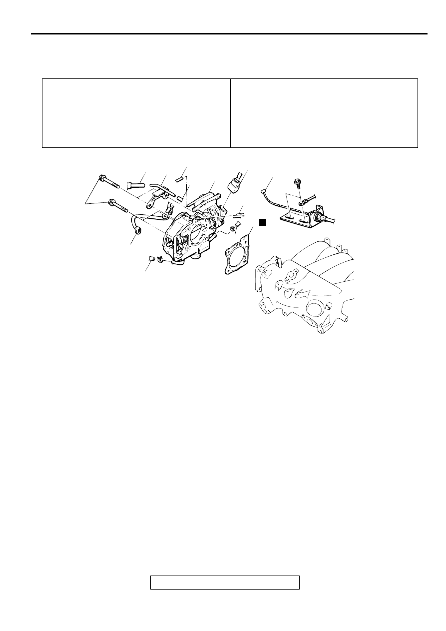
REMOVAL AND INSTALLATION
M1131007700124
Pre-removal Operation
•
Engine Coolant Draining [Refer to GROUP 00, Mainte-
nance Service
−
Engine Coolant (Change)
•
Air Cleaner Removal (Refer to GROUP 15, Air Cleaner
.)
Post-installation Operation
•
Air Cleaner Installation (Refer to GROUP 15, Air Cleaner
.)
•
Engine Coolant Refilling [Refer to GROUP 00, Mainte-
nance Service
−
Engine Coolant (Change)
•
Accelerator Cable Adjustment (Refer to GROUP 17, On-
vehicle Service
−
Accelerator Cable Check and Adjust-
ment
.)
AC001624
4
6
4
4
7
2
1
4
3
5
8
19 ± 3 N·m
14 ± 2 ft-lb
AB
N
5
REMOVAL STEPS
1.
ACCELERATOR CABLE
CONNECTION
2.
THROTTLE POSITION SENSOR
CONNECTOR
3.
IDLE AIR CONTROL MOTOR
CONNECTOR
4.
VACUUM HOSE CONNECTION
5.
WATER HOSE CONNECTION
6.
VACUUM PIPE CONNECTION
7.
THROTTLE BODY
>>A<<
8.
THROTTLE BODY GASKET
REMOVAL STEPS (Continued)
THROTTLE BODY ASSEMBLY
TSB Revision
MULTIPORT FUEL INJECTION (MFI) <3.0L ENGINE>
13B-564
INSTALLATION SERVICE POINT
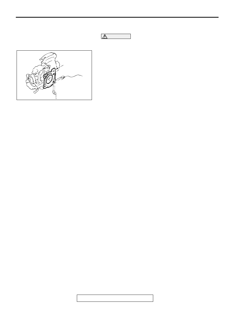
>>A<< THROTTLE BODY GASKET INSTALLATION
CAUTION
Poor idling etc. may result if the throttle body gasket is
installed incorrectly.
Install the throttle body gasket as shown in the illustration.
AC000233
PROJECTION
AB
THROTTLE BODY ASSEMBLY
TSB Revision
MULTIPORT FUEL INJECTION (MFI) <3.0L ENGINE>
13B-565
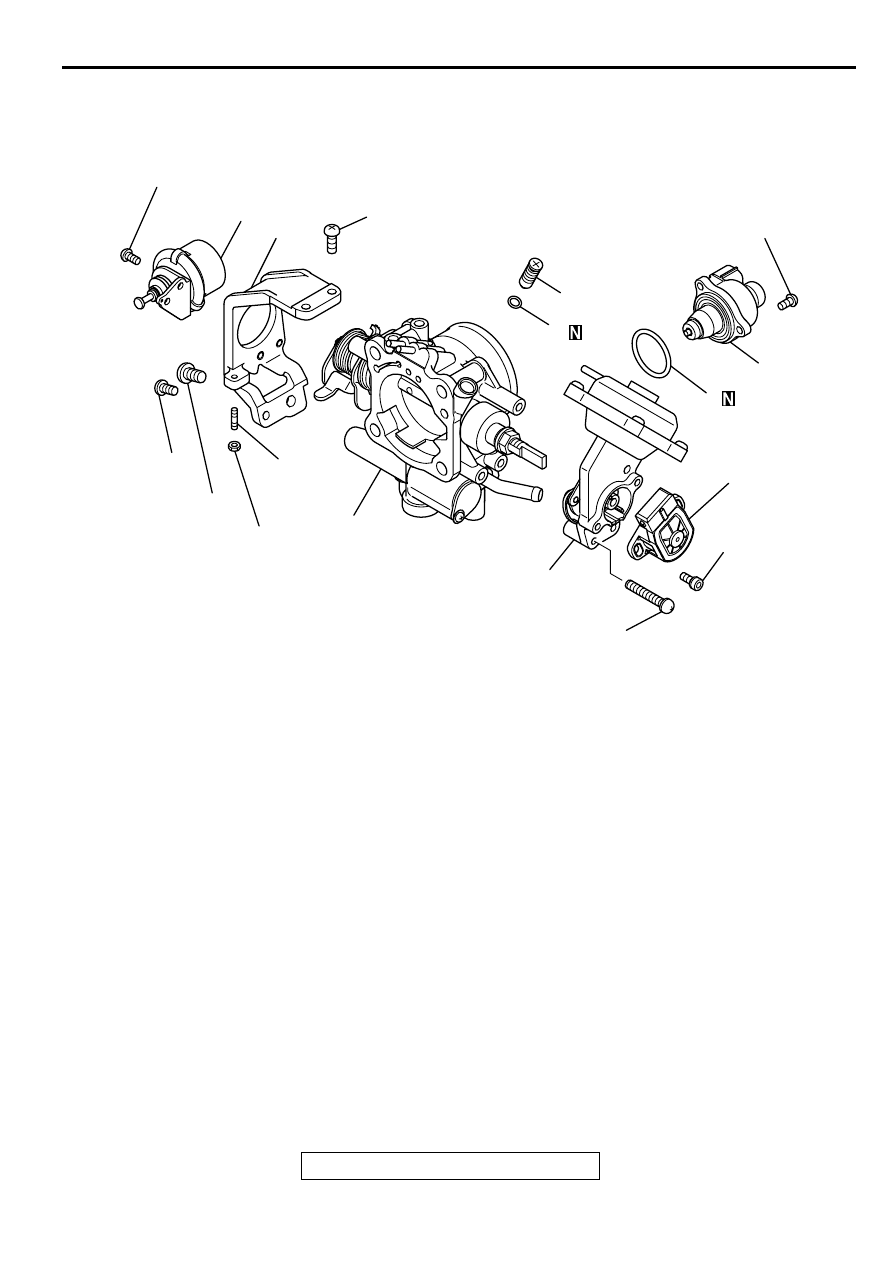
DISASSEMBLY AND ASSEMBLY
M1131009700090
NOTE: IF THE ADJUSTING SCREW WAS HAPPEN
TO HAVE BEEN REMOVED, PERFOM SPEED
ADJUSTING SCREW ADJUSTMENT.
DISASSEMBLY SERVICE POINTS
<<A>> THROTTLE POSITION SENSOR DISASSEMBLY
1. Do not disassemble the sensor and motor.
2. Do not clean the sensor and motor by dipping them into
cleaning solvent. Clean them with shop towel.
AK000206
6
8
7
5
9
10
2
1
4
3
3.4 ± 1 N·m
30 ± 9 in-lb
4.9 ± 1 N·m
43 ± 9 in-lb
4.9 ± 1 N·m
43 ± 9 in-lb
6.9 ± 1.5 N·m
61 ± 13 in-lb
2.0 ± 0.5 N·m
18 ± 4 in-lb
4.9 ± 1 N·m
43 ± 9 in-lb
2.0 ± 0.5 N·m
18 ± 4 in-lb
2.0 ± 0.5 N·m
18 ± 4 in-lb
AB
REMOVAL STEPS
<<A>>
>>A<<
1. THROTTLE POSITION SENSOR
2. LEVER ASSEMBLY
3. IDLE AIR CONTROL MOTOR
4. O-RING
<<B>>
5. THROTTLE BODY
6. DASH POT<M/T>
7. THROTTLE SPEED ADJUSTING
SCREW
8. BRACKET
9. SPEED ADJUSTING SCREW
10.O-RING
REMOVAL STEPS (Continued)
THROTTLE BODY ASSEMBLY
TSB Revision
MULTIPORT FUEL INJECTION (MFI) <3.0L ENGINE>
13B-566
<<B>> THROTTLE BODY DISASSEMBLY
1. Do not disassemble the throttle body.
2. Check if the vacuum port or passage is clogged. Use
compressed air to clean the vacuum passage.
ASSEMBLY SERVICE POINTS
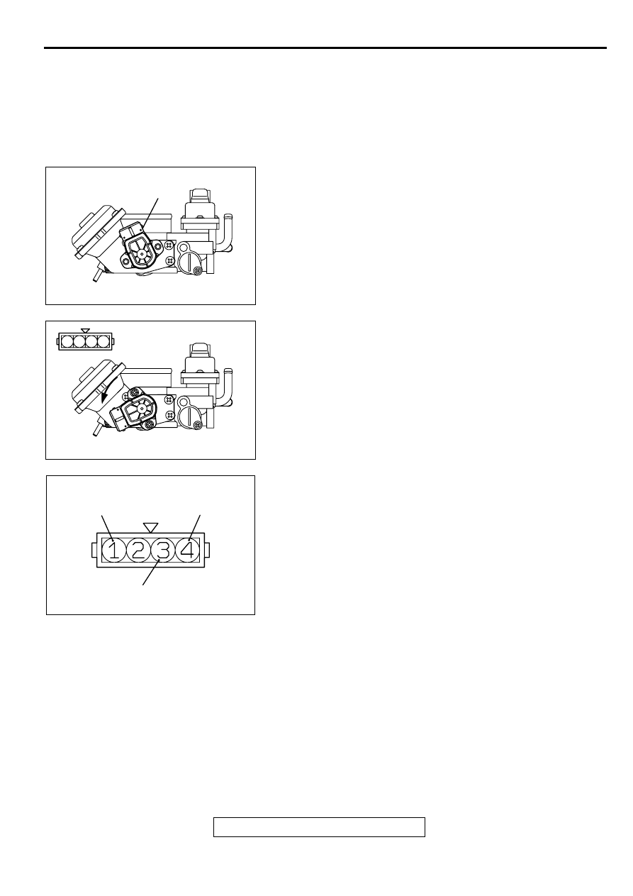
>>A>> THROTTLE POSITION SENSOR (TPS) INSTIGATION
1. Install the throttle position sensor to the throttle body as
shown in the illustration.
2. Turn the throttle position sensor 90 degrees
counterclockwise to set it, and tighten the screws.
3. Connect an ohmmeter between terminals 1 (ground) and 3
(output), or between terminals 3 (output) and 4 (power).
Then, make sure that the resistance changes smoothly
when the throttle valve is slowly moved to the fully open
position.
INSPECTION
M1131009800042
DASH POT
1. Push the dash pot rod in lightly and confirm the resistance.
NOTE: Resistance increases as the rod is pushed harder.
NOTE: If the rod can be pushed in with no resistance, either
the diaphragm or check valve is faulty.
2. Release finger and confirm that the rod returns to it's original
position quickly.
NOTE: If the rod returns slowly, the check valve is faulty.
AK000037
TPS
AB
1 2 3 4
AK000038AB
AKX01635
THROTTLE POSITION
SENSOR POWER
GROUND
THROTTLE POSITION
SENSOR OUTPUT
AB
Нет комментариевНе стесняйтесь поделиться с нами вашим ценным мнением.
Текст