Mitsubishi Eclipse / Eclipse Spyder (2000-2002). Service and repair manual — part 339
ON-VEHICLE SERVICE
TSB Revision
MULTIPORT FUEL INJECTION (MFI) <3.0L ENGINE>
13B-555
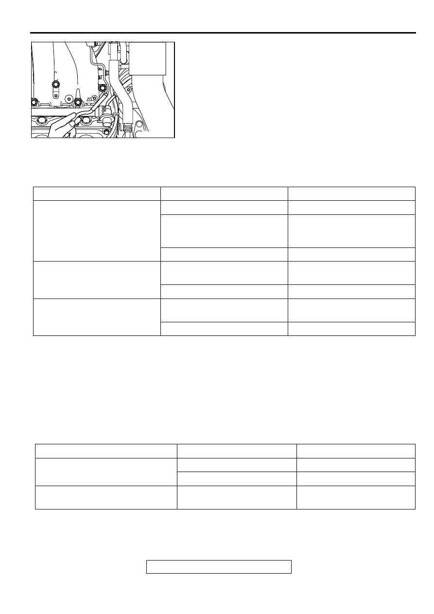
9. Disconnect the vacuum hose (blue stripe) from the fuel
pressure regulator and measure fuel pressure with the hose
end closed with your finger.
Standard value: 330
−
350 kPa (47
−
50 psi) at curb idle
10.Check to see that fuel pressure at idle does not drop even
after the engine has been revved several times.
11.Revving the engine repeatedly, hold the fuel return hose
lightly with your fingers to feel that fuel pressure is present in
the return hose.
NOTE: If the fuel flow rate is low, there will be no fuel
pressure in the return hose.
12.If any of fuel pressure measured in steps 8 to 11 is out of
specification, troubleshoot and repair according to the table
below.
13.Stop the engine and observe fuel pressure gauge reading. It
is normal if the reading does not drop within two minutes. If it
does, observe the rate of drop and troubleshoot and repair
according to the table below. Start, then stop the engine.
(1) Squeeze the fuel return line closed to confirm leak-down
occurs from defective fuel pressure regulator.
(2) Squeeze the fuel supply line closed to confirm leak-down
occurs from defective fuel pump check valve.
(3) If pressure continues to drop with both fuel lines
squeezed closed, injector(s) are leaking.
14.Release residual pressure from the fuel pipe line (Refer to
SYMPTOM
PROBABLE CAUSE
REMEDY
•
Fuel pressure too low
•
Fuel pressure drops after racing
•
No fuel pressure in fuel return
hose
Clogged fuel filter
Replace fuel filter
Fuel leaking to return side due to
poor fuel regulator valve seating or
settled spring
Replace fuel pressure regulator
Low fuel pump delivery pressure
Replace fuel pump
Fuel pressure too high
Binding valve in fuel pressure
regulator
Replace fuel pressure regulator
Clogged fuel return hose or pipe
Clean or replace hose or pipe
Same fuel pressure when vacuum
hose is connected and when
disconnected
Damaged vacuum hose or
clogged nipple
Replace vacuum hose or clean
nipple
Defective fuel pressure regulator
Replace fuel pressure regulator
SYMPTOM
PROBABLE CAUSE
REMEDY
Fuel pressure drops gradually after
engine is stopped
Leaky injector
Replace injector
Leaky fuel regulator valve seat
Replace fuel pressure regulator
Fuel pressure drops sharply
immediately after engine is stopped
Check valve in fuel pump is held
open
Replace fuel pump
AK000119

ON-VEHICLE SERVICE
TSB Revision
MULTIPORT FUEL INJECTION (MFI) <3.0L ENGINE>
13B-556
WARNING
Cover the hose connection with shop towels to
prevent splash of fuel that could be caused by some
residual pressure in the fuel pipe line.
15.Remove the fuel pressure gauge, and special tools
MD998709, MD998742 and MB991637 from the fuel rail.
16.Replace the O-ring at the end of the high-pressure fuel hose
with a new one.
17.Fit the high-pressure fuel hose into the fuel rail and tighten
the bolts to specified torque.
Tightening torque: 4.9
±
1.0 N
⋅
m (43
±
8 in-lb)
18.Check for fuel leaks.
(1) Use scan tool MB991502 to operate the fuel pump.
(2) Check the fuel line for leaks and repair as needed.
19.Disconnect scan tool MB991502.
FUEL PUMP CONNECTOR
DISCONNECTION(HOW TO REDUCE
PRESSURIZED FUEL LINES)
M1131000900161
Refer to GROUP 13A, On-vehicle Service
−
Fuel Pump Relay
Disconnection (How to Reduce Pressurized Fuel Lines)
FUEL PUMP OPERATION CHECK
M1131002000153
Refer to GROUP 13A, On-vehicle Service
−
Fuel Pump
Operation Check
MULTIPORT FUEL INJECTION (MFI) RELAY AND
FUEL PUMP RELAY CONTINUITY CHECK
M1131009900094
Refer to GROUP 13A, On-vehicle Service
−
Multiport Fuel
Injection (MFI) Relay and Fuel Pump Relay Continuity Check
(
INTAKE AIR TEMPERATURE SENSOR CHECK
M1131002800085
Refer to GROUP 13A, On-vehicle Service
−
Intake Air
Temperature Sensor Check (
ENGINE COOLANT TEMPERATURE SENSOR
CHECK
M1131003100089
Refer to GROUP 13A, On-vehicle Service
−
Engine Coolant
Temperature Sensor Check (
ON-VEHICLE SERVICE
TSB Revision
MULTIPORT FUEL INJECTION (MFI) <3.0L ENGINE>
13B-557
THROTTLE POSITION SENSOR CHECK
M1131003200064
Required Special Tool:
MB991348: Test Harness Set
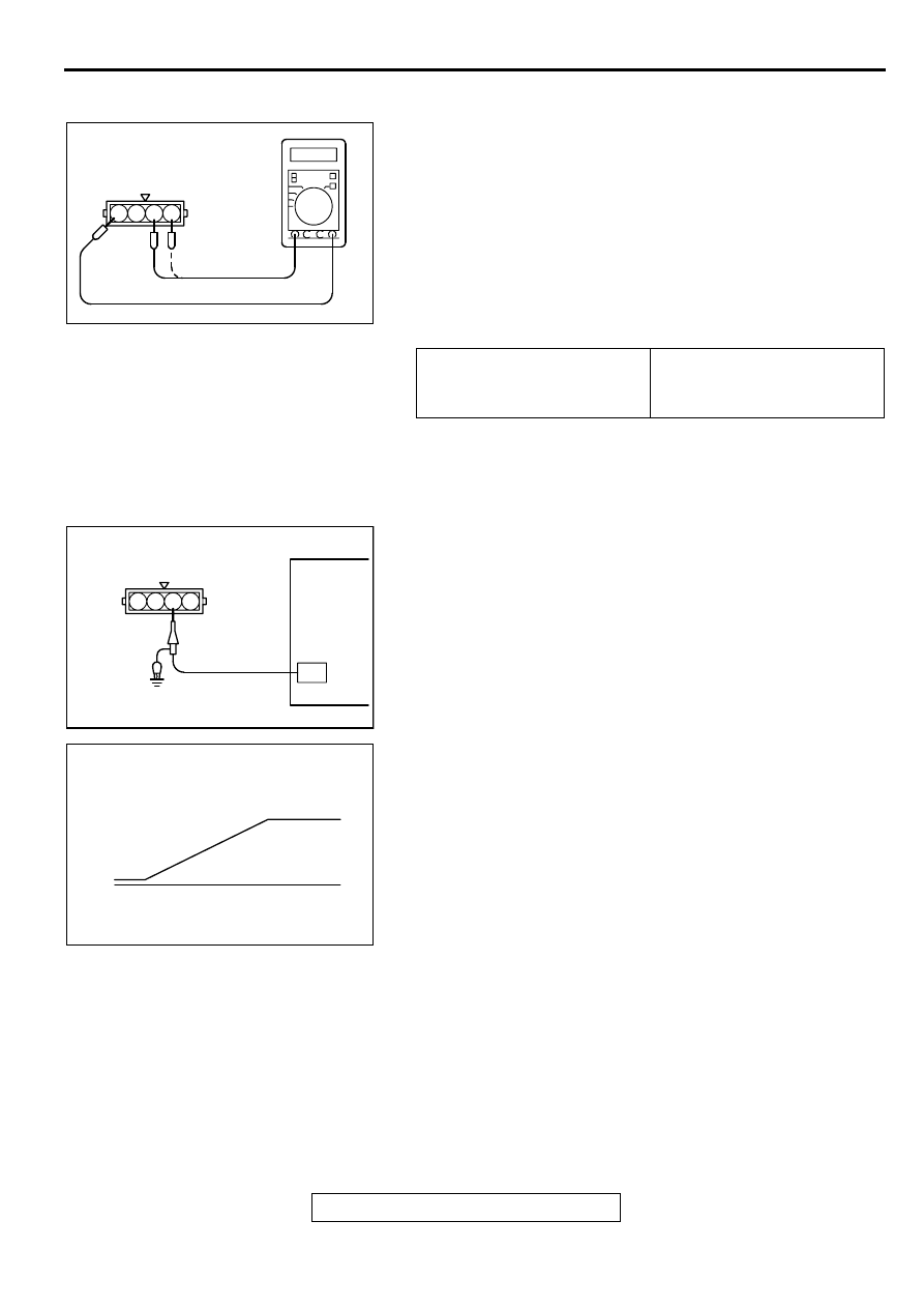
Checking the Terminal Resistance
1. Disconnect the throttle position sensor connector.
2. Measure the resistance between throttle position sensor
side connector terminals 1 and 4.
Standard value: 3.5
−
6.5 k
Ω
3. Measure the resistance between throttle position sensor
side connector terminals 1 and terminal 3.
Normal condition:
4. If the resistance is outside the standard value, or if it doesn't
change smoothly, replace the throttle position sensor.
NOTE: After replacement, the throttle position sensor should
be adjusted. (Refer to
.)
Check using oscilloscope
1. Disconnect the throttle position sensor connector and
connect the test harness special tool (MB991348) in
between.(All terminals should be connected.)
2. Connect the oscilloscope probe to the throttle position
sensor side connector terminal 3.
3. Turn the ignition switch to the "ON" position.
4. Slowly move the throttle lever from the idle position to the
full-throttle position and check then if the waveform is free
from any noise.
5. If any noise is recognized, replace the throttle position
sensor.
NOTE: After replacement, the throttle position sensor should
be adjusted. (Refer to
.)
HEATED OXYGEN SENSOR CHECK
M1131005000107
Required Special Tools:
MD998464: Test Harness
MB991316: Test Harness
MB991658: Test Harness Set
Throttle valve slowly open
until fully open from the idle
position
Changes smoothly in
proportion to the opening
angle of the throttle valve
AKX01413
THROTTLE POSITION
SENSOR CONNECTOR
1 2 3 4
AB
AKX01461AB
THROTTLE POSITION
SENSOR CONNECTOR
OSCILLOSCOPE
1 2 3 4
AKX01462AB
NORMAL WAVEFORM
THROTTLE LEVER
FULL-THROTTLE
POSITION
THROTTLE
LEVER
IDLE
POSITION
ON-VEHICLE SERVICE
TSB Revision
MULTIPORT FUEL INJECTION (MFI) <3.0L ENGINE>
13B-558
<Right bank and left bank heated oxygen sensor (front)>
1. Use scan tool MB991502, observe HO
2
S reading. If values
are unsatisfactory, or if the scan tool is not available, use the
following procedure:
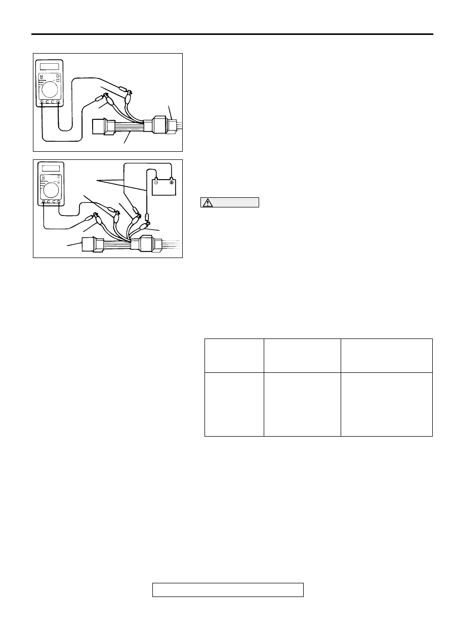
(1) Disconnect the heated oxygen sensor connector and
connect special tool MD998464 to the connector on the
heated oxygen sensor side.
(2) Make sure that there is continuity [4.5
−
8.0 ohm at 20
°
C
(68
°
F
)
] between terminal 1 (red clip of special tool) and
terminal 3 (blue clip of special tool) on the heated oxygen
sensor connector.
(3) If there is no continuity, replace the heated oxygen
sensor.
(4) Warm up the engine until engine coolant is 80
°
C (176
°
F
)
ορ ηιγηερ.
CAUTION
Be very careful when connecting the jumper wires;
incorrect connection can damage the heated oxygen
sensor.
(5) Use the jumper wires to connect terminal 1 (red clip) of
the heated oxygen sensor connector to the positive
battery terminal and terminal 3 (blue clip) to the negative
battery terminal.
(6) Connect a digital voltage meter between terminal 2 (black
clip) and terminal 4 (white clip).
2. While repeatedly revving the engine, measure the heated
oxygen sensor output voltage.
Standard value:
3. If the sensor is defective, replace the heated oxygen sensor.
NOTE: For removal and installation of the heated oxygen
sensor, refer to GROUP 15, Exhaust Pipe and Main Muffler
(
ENGINE
HEATED OXYGEN
SENSOR OUTPUT
VOLTAGE
REMARKS
When revving
engine
0.6
−
1.0V
If you make the air/fuel
ratio rich by revving the
engine repeatedly, a
normal heated oxygen
sensor will output a
voltage of 0.6
−
1.0V.
AKX01624
HEATED
OXYGEN
SENSOR
EQUIPMENT
SIDE
CONNECTOR
MD998464
BLUE
RED
AC
AKX01625AC
BLUE
RED
BLACK
JUMPER
WIRES
WHITE
MD998464
Нет комментариевНе стесняйтесь поделиться с нами вашим ценным мнением.
Текст