Mitsubishi Eclipse / Eclipse Spyder (2000-2002). Service and repair manual — part 342
SPECIFICATIONS
TSB Revision
MULTIPORT FUEL INJECTION (MFI) <3.0L ENGINE>
13B-567
SPECIFIC ATIO NS
FASTENER TIGHTENING SPECIFICATION
M1131011600186
GENERAL SPECIFICATIONS
M1131000200139
ITEM
SPECIFICATION
Dashpot
3.4
±
1.0 N
⋅
m (30
±
9 in-lb)
Engine coolant temperature sensor
29
±
10 N
⋅
m (22
±
7 ft-lb)
Fuel rail mounting bolt
12
±
1 N
⋅
m (100
±
13 in-lb)
Fuel pressure regulator
8.8
±
1.0 N
⋅
m (78
±
9 in-lb)
High-pressure fuel hose
4.9
±
1.0 N
⋅
m (44
±
8 in-lb)
Idle air control motor
2.0
±
0.5 N
⋅
m (18
±
4 in-lb)
Lever assembly
4.9
±
1.0 N
⋅
m (43
±
9 in-lb)
Throttle body bracket M6
4.9
±
1.0 N
⋅
m (44
±
8 in-lb)
Throttle body bracket M8
6.9
±
1.5 N
⋅
m (61
±
13 in-lb)
Throttle body to intake manifold bolt
19
±
3 N
⋅
m (14
±
2 ft-lb)
Throttle position sensor
2.0
±
0.5 N
⋅
m (18
±
4 in-lb)
Throttle speed adjusting screw mounting bolt
2.0
±
0.5 N
⋅
m (18
±
4 in-lb)
ITEMS
SPECIFICATIONS
Throttle body
Throttle bore mm (in.)
60 (2.4)
Throttle position sensor
Variable resistor type
Idle air control motor
Stepper motor (stepper motor type by-
pass air control system with the air
volume limiter)
Engine control module
(ECM) <M/T>
Identification model No.
E2T73083
Powertrain control
module (PCM) <A/T>
Identification model No.
E2T70291
Sensors
Volume air flow sensor
Karman vortex type
Barometric pressure sensor
Semiconductor type
Intake air temperature sensor
Thermistor type
Engine coolant temperature sensor
Thermistor type
Heated oxygen sensor
Zirconia type
Vehicle speed sensor
Electromagnetic resistance element type
Park/neutral position switch <A/T>
Contact switch type
Camshaft position sensor
Electromagnetic resistance element type
Crankshaft position sensor
Hall element type
Knock sensor
Piezoelectric type
Power steering pressure switch
Contact switch type
Manifold differential pressure sensor
Semiconductor type
SPECIFICATIONS
TSB Revision
MULTIPORT FUEL INJECTION (MFI) <3.0L ENGINE>
13B-568
SERVICE SPECIFICATIONS
M1131000300062
SEALANT
M1131000500022
Actuators
Multiport fuel injection (MFI) relay
Contact switch type
Fuel pump relay
Contact switch type
Injector type and number
Electromagnetic type, 6
Injector identification mark
CDH210
EGR solenoid
Duty cycle type solenoid valve
Evaporative emission purge solenoid
Duty cycle type solenoid valve
Fuel pressure regulator Regulator pressure kPa (psi)
335 (47.6)
ITEMS
SPECIFICATIONS
ITEMS
STANDARD VALUE
Throttle position sensor adjusting voltage mV
535
−
735
Basic idle speed r/min
700
±
50
Fuel pressure kPa (psi)
Vacuum hose disconnected 330
−
350 (47
−
50) at curb idle
Vacuum hose connected
Approximately 270 (38) at curb idle
Intake air temperature sensor
resistance k
Ω
0
°
C (32
°
F)
5.3
−
6.7
20
°
C (86
°
F)
2.3
−
3.0
40
°
C (104
°
F)
1.0
−
1.5
80
°
C (176
°
F)
0.30
−
0.42
Engine coolant temperature sensor
resistance k
Ω
0
°
C (32
°
F)
5.1
−
6.5
20
°
C (68
°
F)
2.1
−
2.7
40
°
C (104
°
F)
0.9
−
1.3
80
°
C (176
°
F)
0.26
−
0.36
Throttle position sensor resistance k
Ω
3.5
−
6.5
Heated oxygen sensor output voltage V
0.6
−
1.0
Heated oxygen sensor heater
resistance
Ω
Front
4.5
−
8.0
Rear
11
−
18
Injector coil resistance
Ω
13
−
16 [at 20
°
C (68
°
F)]
Idle air control motor coil resistance
Ω
28
−
33 [at 20
°
C (68
°
F)]
ITEM
SPECIFIED SEALANT
Engine coolant temperature sensor threaded portion 3M
AAD part number 8731or equivalent
14-1
GROUP 14
CONTENTS
GENERAL DESCRIPTION. . . . . . . . .
ENGINE COOLING SYSTEM
DIAGNOSIS . . . . . . . . . . . . . . . . . . . .
INTRODUCTION TO ENGINE COOLING
DIAGNOSIS . . . . . . . . . . . . . . . . . . . . . . . .
TROUBLESHOOTING STRATEGY . . . . . .
SYMPTOM CHART. . . . . . . . . . . . . . . . . . .
SYMPTOM PROCEDURES . . . . . . . . . . . .
ON-VEHICLE SERVICE. . . . . . . . . . .
ENGINE COOLANT LEAK CHECK . . . . . .
RADIATOR CAP PRESSURE CHECK. . . .
ENGINE COOLANT REPLACEMENT . . . .
ENGINE COOLANT CONCENTRATION
TEST . . . . . . . . . . . . . . . . . . . . . . . . . . . . . .
FAN CONTROLLER CHECK . . . . . . . . . . .
FAN CONTROL RELAY CONTINUITY
CHECK . . . . . . . . . . . . . . . . . . . . . . . . . . . .
RADIATOR . . . . . . . . . . . . . . . . . . . . .
REMOVAL AND INSTALLATION . . . . . . . .
THERMOSTAT . . . . . . . . . . . . . . . . . .
REMOVAL AND INSTALLATION . . . . . . . .
INSPECTION. . . . . . . . . . . . . . . . . . . . . . . .
WATER PUMP . . . . . . . . . . . . . . . . . .
REMOVAL AND INSTALLATION . . . . . . . .
WATER HOSE AND WATER PIPE . .
REMOVAL AND INSTALLATION . . . . . . . .
INSPECTION. . . . . . . . . . . . . . . . . . . . . . . .
SPECIFICATIONS . . . . . . . . . . . . . . .
FASTENER TIGHTENING
SPECIFICATIONS. . . . . . . . . . . . . . . . . . . .
SERVICE SPECIFICATIONS . . . . . . . . . . .
LUBRICANT . . . . . . . . . . . . . . . . . . . . . . . .
GENERAL DESCRIPTION
TSB Revision
COOLING SYSTEM
14-2
.
G EN ER A L DESC RIPTIO N
M1141000100100
The cooling system is designed to keep every part of
the engine at appropriate temperature in whatever
condition the engine may be operated. The cooling
method is of the water-cooled, pressure forced
circulation type in which the water pump pressurizes
coolant and circulates it throughout the engine. If the
coolant temperature exceeds the prescribed
temperature, the thermostat opens to circulate the
coolant through the radiator as well so that the heat
absorbed by the coolant may be radiated into the air.
The water pump is of the centrifugal type and is
driven by the drive belt from the crankshaft. The
radiator is the corrugated fin, down flow type and is
cooled by an electrical radiator fan. And if the engine
coolant temperature reaches 110
°
C(230
°
F) or
higher, the radiator fan control rotates the radiator
fan for up to 5 minutes even after the ignition switch
is turned to the "LOCK (OFF)" position [the fan stops
its rotation when the engine coolant temperature
decreases to 110
°
C (230
°
F) or lower].
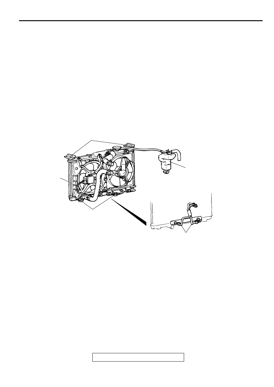
CONSTRUCTION DIAGRAM
EN G IN E C O O LIN G D IA G N O SIS
INTRODUCTION TO ENGINE COOLING DIAGNOISIS
M1141005300121
The system cools the engine so that it does not
overheat and maintains the engine at an optimum
temperature. The system components are the
radiator, water pump, thermostat, condenser fan
assembly. Possible faults include low coolant,
contamination, belt loosening and component
damage.
AC004034 AB
A/T OIL COOLER HOSE
RESERVE TANK
LOWER INSULATOR
RADIATOR
RADIATOR SUPPORT
Нет комментариевНе стесняйтесь поделиться с нами вашим ценным мнением.
Текст