Mitsubishi Eclipse / Eclipse Spyder (2000-2002). Service and repair manual — part 682
SRS AIR BAG DIAGNOSIS
TSB Revision
SUPPLEMENTAL RESTRAINT SYSTEM (SRS)
52B-55
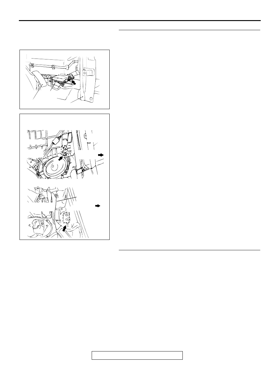
STEP 2. Check the harness wires between SRS-ECU
connector C-74 and side impact sensor (RH) connector D-
02.
Q: Are the harness wires between SRS-ECU connector C-
74 and side impact sensor (RH) connector D-02 in good
condition?
YES : Go to Step 3.
NO : Repair them. Then go to Step 3.
STEP 3. Check for DTC.
Q: Is DTC 94 output?
YES : Replace the SRS-ECU. Refer to
NO : This diagnosis is compleate.(If no malfunctions are
not found in all steps, an intermittent malfunction is
suspected. Refer to GROUP 00, How to Use
Troubleshooting/Inspection Service Points
−
How to
Cope with Intermittent Malfunction
.)
AC000358AF
CONNECTOR: C-74
SRS-ECU
ACCELERATOR PEDAL
CENTER REINFORCEMENT (LH)
AC003136AB
CONNECTOR: D-02
<ECLIPSE>
<ECLIPSE SPYDER>
FRONT
SEAT BELT
FRONT OF
VEHICLE
REAR
SPEAKER
FRONT
SEAT BELT
FRONT OF
VEHICLE
REAR SPEAKER
BRACKET
SRS AIR BAG DIAGNOSIS
TSB Revision
SUPPLEMENTAL RESTRAINT SYSTEM (SRS)
52B-56
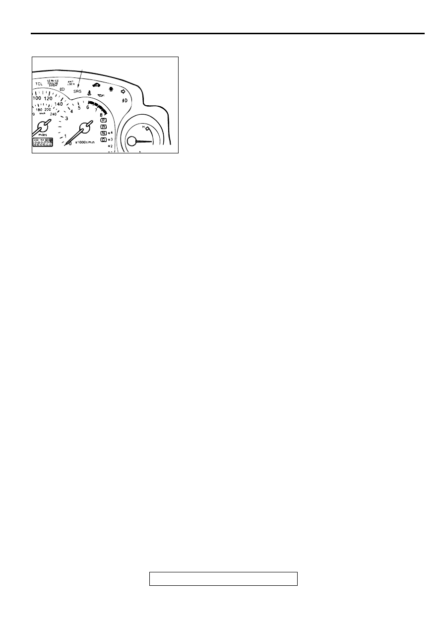
SRS WARNING LIGHT CHECK
M1524004300060
1. Check that the SRS warning light illuminates when the
ignition switch is in the "ON" position.
2. Check that it illuminates for approximately 7 seconds and
then goes out.
3. If not, check for DTC.
AC000346AB
SRS WARNING LIGHT
SRS AIR BAG DIAGNOSIS
TSB Revision
SUPPLEMENTAL RESTRAINT SYSTEM (SRS)
52B-57
SYMPTOM PROCEDURES
M1524010300047
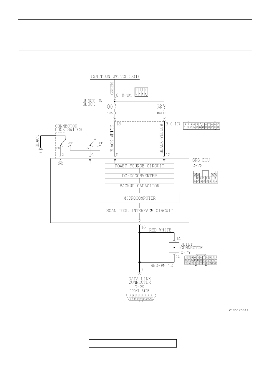
INSPECTION PROCEDURE 1: Communication with scan tool MB991502 is not possible with the SRS
system only.
AC002969AB
SRS-ECU Power Supply Circuit
SRS AIR BAG DIAGNOSIS
TSB Revision
SUPPLEMENTAL RESTRAINT SYSTEM (SRS)
52B-58
CIRCUIT OPERATION
•
The SRS-ECU is powered from the ignition
switch (IG1).
•
The SRS-ECU power is supplied from two
circuits. Even if one circuit is shut off, the air bag
can inflate.
•
The SRS system diagnosis can be done by
connecting scan tool MB991502 to the data link
connector.
•
The SRS-ECU judges how severe a collision is
by detecting signals from the left and right side
impact sensors and the analog G-sensor. If the
impact is over a predetermined level, the SRS-
ECU outputs an ignition signal. At this time, if the
safing G-sensor is on, the SRS air bag will inflate.
TECHNICAL DESCRIPTION (COMMENT)
•
If communication is not possible with the SRS
only, the cause is probably an open circuit in the
on-board diagnostic output circuit of the SRS or
in the power circuit (including ground circuit).
TROUBLESHOOTING HINTS
•
Damaged wiring harnesses or connectors
•
Malfunction of the SRS-ECU
DIAGNOSIS
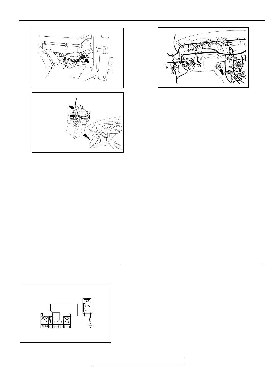
STEP 1. Check the ground line at the SRS-ECU connector
C-72 by backprobing.
(1) Do disconnect the connector C-72.
(2) Check the continuity between terminal 3 and the ground by
backprobing.
Q: Is the resistance between terminal 3 and ground less
than 2 ohm?
YES : Go to Step 3.
NO : Go to Step 2.
AC000358AD
SRS-ECU
ACCELERATOR PEDAL
CENTER REINFORCEMENT(LH)
CONNECTOR: C-72
AC000366AC
CONNECTOR: C-101, C-107
C-101
C-107
JUNCTION
BLOCK
(FRONT VIEW)
AC000800AC
CONNECTOR: C-29
COMBINATION METER
AC000368AC
C-72 CONNECTOR HARNESS SIDE VIEW
Нет комментариевНе стесняйтесь поделиться с нами вашим ценным мнением.
Текст