Mitsubishi Eclipse / Eclipse Spyder (2000-2002). Service and repair manual — part 206
MULTIPORT FUEL INJECTION (MFI) DIAGNOSIS
TSB Revision
MULTIPORT FUEL INJECTION (MFI) <3.0L ENGINE>
13B-23
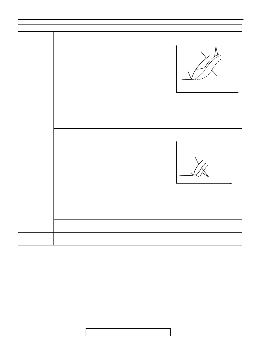
Driving
Hesitation Sag
" Hesitation " is the delay in
response of the vehicle speed
(engine speed). This occurs when
the accelerator is depressed in
order to accelerate from the speed
at which the vehicle is now
traveling, or a temporary drop in
vehicle speed (engine speed)
during such acceleration.
Serious hesitation is called " sag. "
Poor
acceleration
Poor acceleration is inability to obtain an acceleration corresponding to
the degree of throttle opening, even though acceleration is smooth or
the inability to reach maximum speed.
Stumble
Engine speed increase is delayed
when the accelerator pedal is
initially depressed for acceleration.
Shock
The feeling of a comparatively large impact or vibration when the
engine is accelerated or decelerated.
Surge
This is slight acceleration and deceleration feel usually felt during
steady, light throttle cruise. Most notable under light loads.
Knocking
A sharp sound during driving usually work aloud. It sounds like a
hammer striking the cylinder walls. It adversely affects driving.
Stopping
(Run on)
"Dieseling"
The condition in which the engine continues to run after the ignition
switch is turned to the "LOCK" (OFF) position. Also called "dieseling."
ITEMS
SYMPTOM
AKX01361
VEHICLE
SPEED
TIME
NORMAL
HESITATION
SAG
INITIAL
ACCELE-
RATOR
PEDAL
DEPRE-
SSION
AKX01361AB
AKX01362
VEHICLE
SPEED
TIME
NORMAL
STUMBLE
INITIAL
ACCEL-
ERATOR
PEDAL
DEP-
RESSION
IDLING
MULTIPORT FUEL INJECTION (MFI) DIAGNOSIS
TSB Revision
MULTIPORT FUEL INJECTION (MFI) <3.0L ENGINE>
13B-24
DIAGNOSTIC TROUBLE CODE PROCEDURES
DTC P0101: Volume Air Flow Circuit Range/Performance Problem
AK000685
65
43
50
42
49
41
48
60 61
64
46 47
58 59
67 68
45
56
66
52
51
44
53
62
54
63
57
55
1 2 3 4 5 6 7
RED
RED
-
WHITE
RED
-
WHITE
3 4
1 2
RED
-
WHITE
GREEN-BL
UE
BL
ACK
WHITE-GREEN
B-14
BATTERY
VOLUME AIR
FLOW SENSOR
5V
19<M/T>*1
19<A/T>*3
7
4
5
3
ENGINE CONTROL
MODULE(ECM)<M/T>
OR
POWERTRAIN CONTROL
MODULE(PCM)<A/T>
A-21X
MFI
RELAY
3
4
1
2
49<M/T>*2
57<A/T>*4
61<M/T>*2
65<A/T>*4
C-51<M/T>,C-52<A/T>
(MU803784)
C-58<M/T>
(MU803782)
C-55<A/T>
(MU803781)
NOTE
*1:ECM connector C-51<M/T>
*2:ECM connector C-58<M/T>
*3:PCM connector C-52<A/T>
*4:PCM connector C-55<A/T>
2
3 4
5 6
7 8
9
11 12 13 14 15 16 17 18 19 20
30
21 22 23
24 25
26 27 28 29
3132 33
34 35
1
10
42 43
48 49 50 51 52 53 54 55 56 57
46
45
44
58 59
60 61 62 63
64 65 66
47
41
MULTIPORT FUEL INJECTION (MFI) DIAGNOSIS
TSB Revision
MULTIPORT FUEL INJECTION (MFI) <3.0L ENGINE>
13B-25
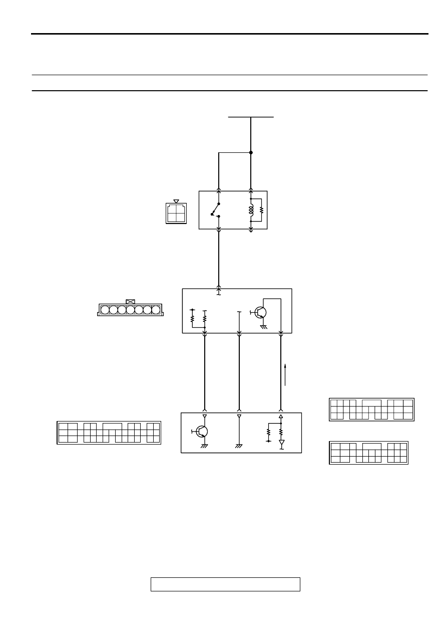
CIRCUIT OPERATION
•
The volume air flow sensor power is supplied
from the MFI relay (terminal 1), and the ground is
provided on the ECM (terminal 49) <M/T> or
PCM (terminal 57) <A/T>.
•
5-volt power is applied to the volume air flow
sensor output terminal (terminal 3) from the ECM
(terminal 61) <M/T> or PCM (terminal 65) <A/T>.
The volume air flow sensor generates a pulse
signal when the output terminal and ground are
opened/closed (opened/short).
TECHNICAL DESCRIPTION
•
While the engine is running, the volume air flow
sensor outputs a pulse signal which corresponds
to the volume of air flow.
•
The ECM <M/T> or PCM <A/T> checks whether
the frequency of this signal output by the volume
air flow sensor while the engine is running is at or
above the set value.
DTC SET CONDITIONS
Check Conditions
•
Engine speed is higher than 500 r/min.
Judgement Criteria
•
Volume air flow sensor output frequency has
continued to be 3.3 Hz or lower for 2 seconds.
TROUBLESHOOTING HINTS (The most likely
causes for this code to be set are:)
•
Volume air flow sensor failed.
•
Open or shorted volume air flow sensor circuit, or
loose connector.
•
ECM failed. <M/T>
•
PCM failed. <A/T>
•
Air leak between volume air flow sensor and
throttle body.
DIAGNOSIS
Required Special Tools
MB991502: Scan Tool (MUT-II)
ACX02480
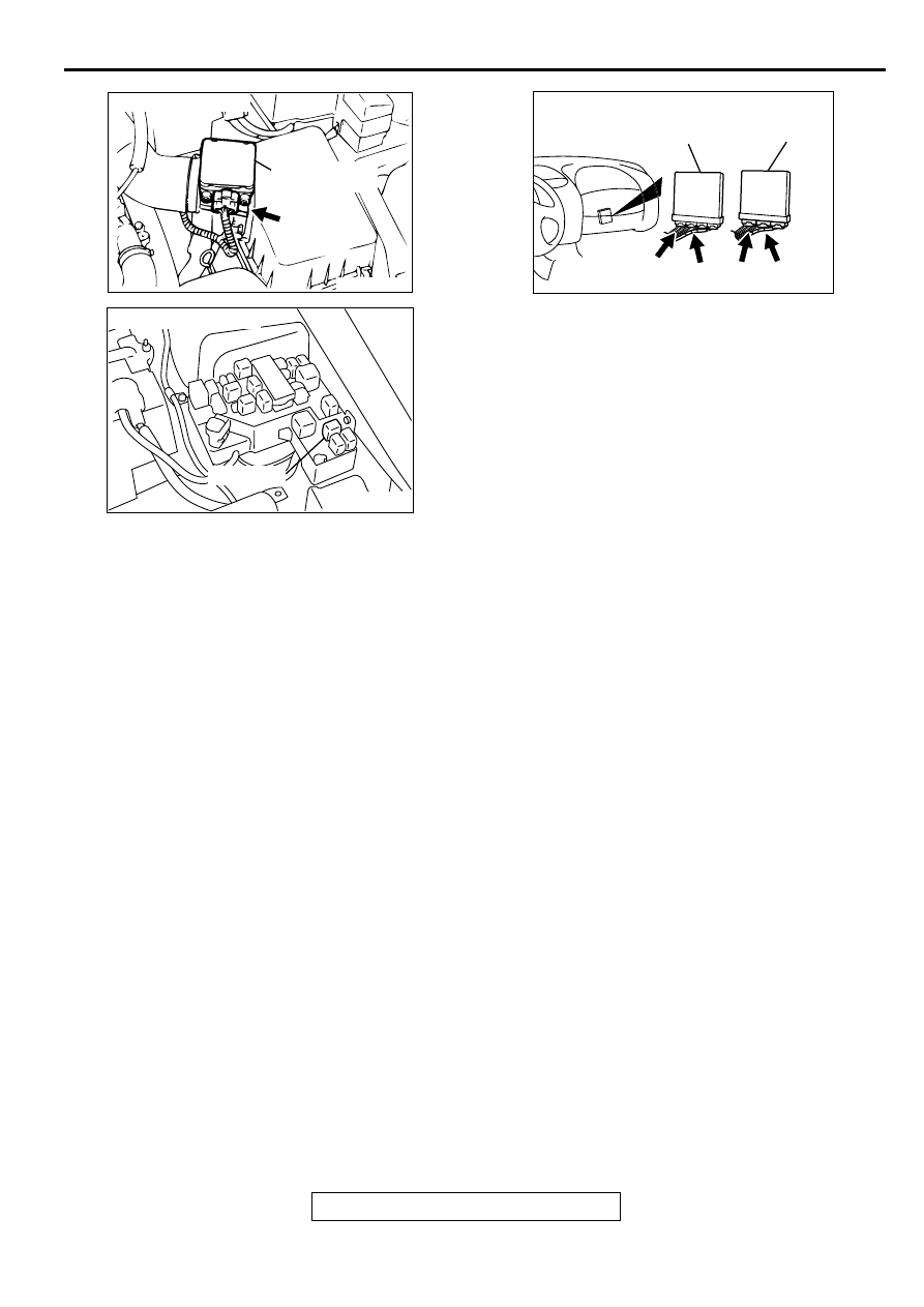
CONNECTOR : B-14
AC
VOLUME AIR
FLOW SENSOR
AK000226
AK000226AB
CONNECTOR : A-21X
MFI RELAY
AK000225
C-52
C-55
C-51
C-58
CONNECTORS:C-51,C-58<M/T>
C-52,C-55<A/T>
ECM<M/T>
PCM<A/T>
AH
MULTIPORT FUEL INJECTION (MFI) DIAGNOSIS
TSB Revision
MULTIPORT FUEL INJECTION (MFI) <3.0L ENGINE>
13B-26
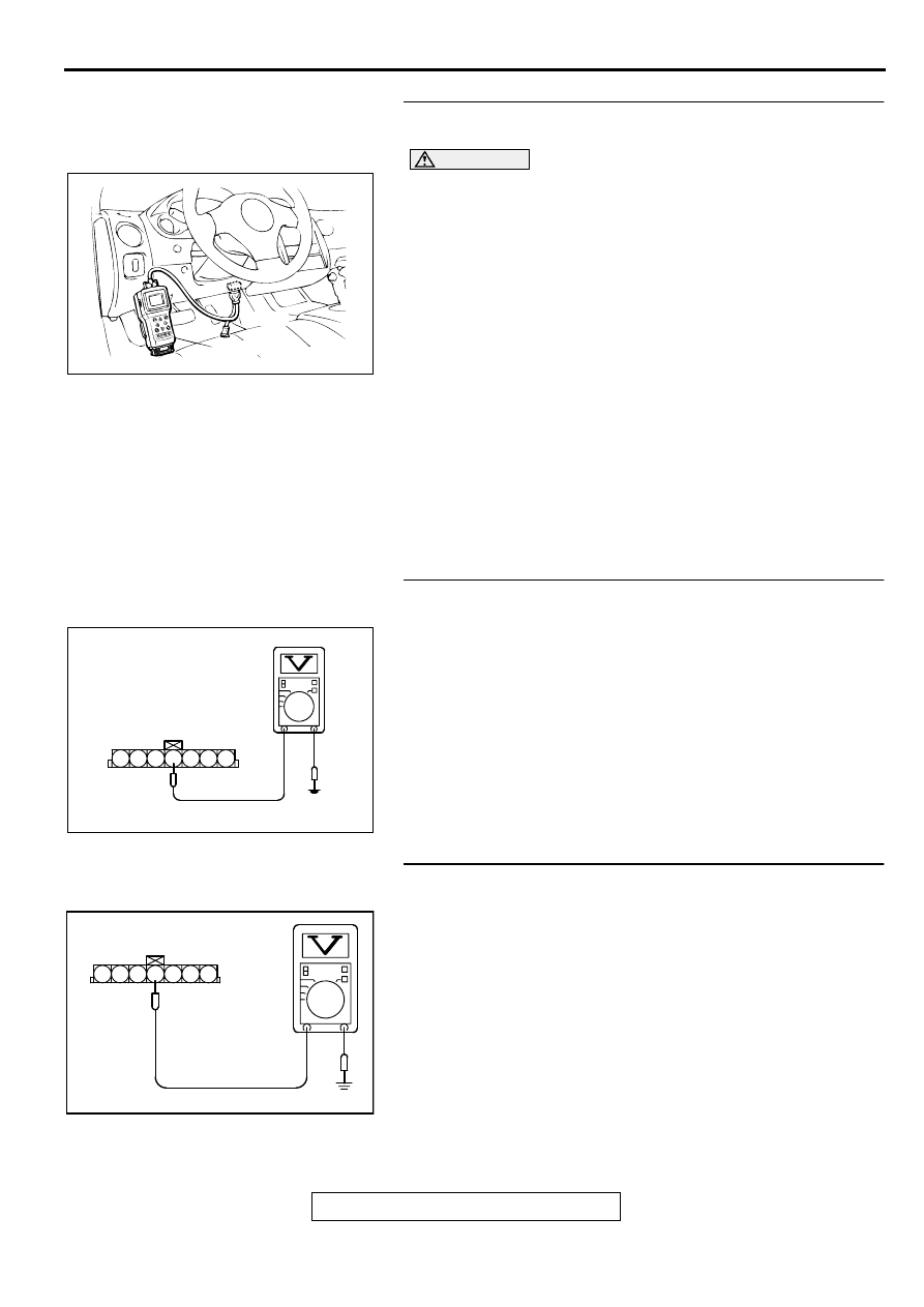
STEP 1. Using scan tool MB991502, check data list item 12:
Volume Air Flow Sensor.
CAUTION
To prevent damage to scan tool MB991502, always turn the
ignition switch to the "LOCK" (OFF) position before
connecting or disconnecting scan tool MB991502.
(1) Connect scan tool MB991502 to the data link connector.
(2) Start the engine and run at idle.
(3) Set scan tool MB991502 to the data reading mode for item
12, Volume Air Flow Sensor.
(4) Warm up the engine to normal operating temperature: 80
°
C
to 96
°
C (176
°
F to 205
°
F).
•
The standard value during idling should be 10Hz or
more.
•
When the engine is revved, the frequency should
increase according to the increase in engine speed.
(5) Turn the ignition switch to the "LOCK" (OFF) position.
Q: Is the sensor operating properly?
YES : It can be assumed that this malfunction is intermittent.
Refer to GROUP 00, How to Use Troubleshooting/
Inspection Service Points (
NO : Go to Step 2.
STEP 2. Check the power supply voltage at volume air flow
sensor connector B-14 by backprobing.
(1) Do not disconnect the connector B-14.
(2) Turn the ignition switch to the "ON" position.
(3) Measure the voltage between terminal 4 and ground by
backprobing.
•
Voltage should be battery positive voltage.
(4) Turn the ignition switch to the "LOCK" (OFF) position.
Q: Is the voltage normal?
YES : Go to Step 5.
NO : Go to Step 3.
STEP 3. Check the power supply voltage at volume air flow
sensor harness side connector B-14.
(1) Disconnect the connector B-14 and measure at the harness
side.
(2) Turn the ignition switch to the "ON" position.
(3) Measure the voltage between terminal 4 and ground.
•
Voltage should be battery positive voltage.
(4) Turn the ignition switch to the "LOCK" (OFF) position.
Q: Is the voltage normal?
YES : Go to Step 4.
NO : Repair harness wire between MFI relay connector A-
21X terminal 1 and volume air flow sensor connector
B-14 terminal 4 because of open circuit or short
circuit to ground. Then go to Step 13.
AKX01177
16 PIN
MB991502
AB
AKX01514 AD
B-14 CONNECTOR
HARNESS SIDE VIEW
1 2 3 4 5 6 7
AKX01405
B-14 HARNESS
SIDE CONNECTOR
7 6 5 4 3 2 1
AC
Нет комментариевНе стесняйтесь поделиться с нами вашим ценным мнением.
Текст