Mitsubishi Eclipse / Eclipse Spyder (2000-2002). Service and repair manual — part 204
MULTIPORT FUEL INJECTION (MFI) DIAGNOSIS
TSB Revision
MULTIPORT FUEL INJECTION (MFI) <3.0L ENGINE>
13B-15
PROCEDURE 5
EXHAUST GAS RECIRCULATION (EGR) SYSTEM MONITOR
DTC
P0401
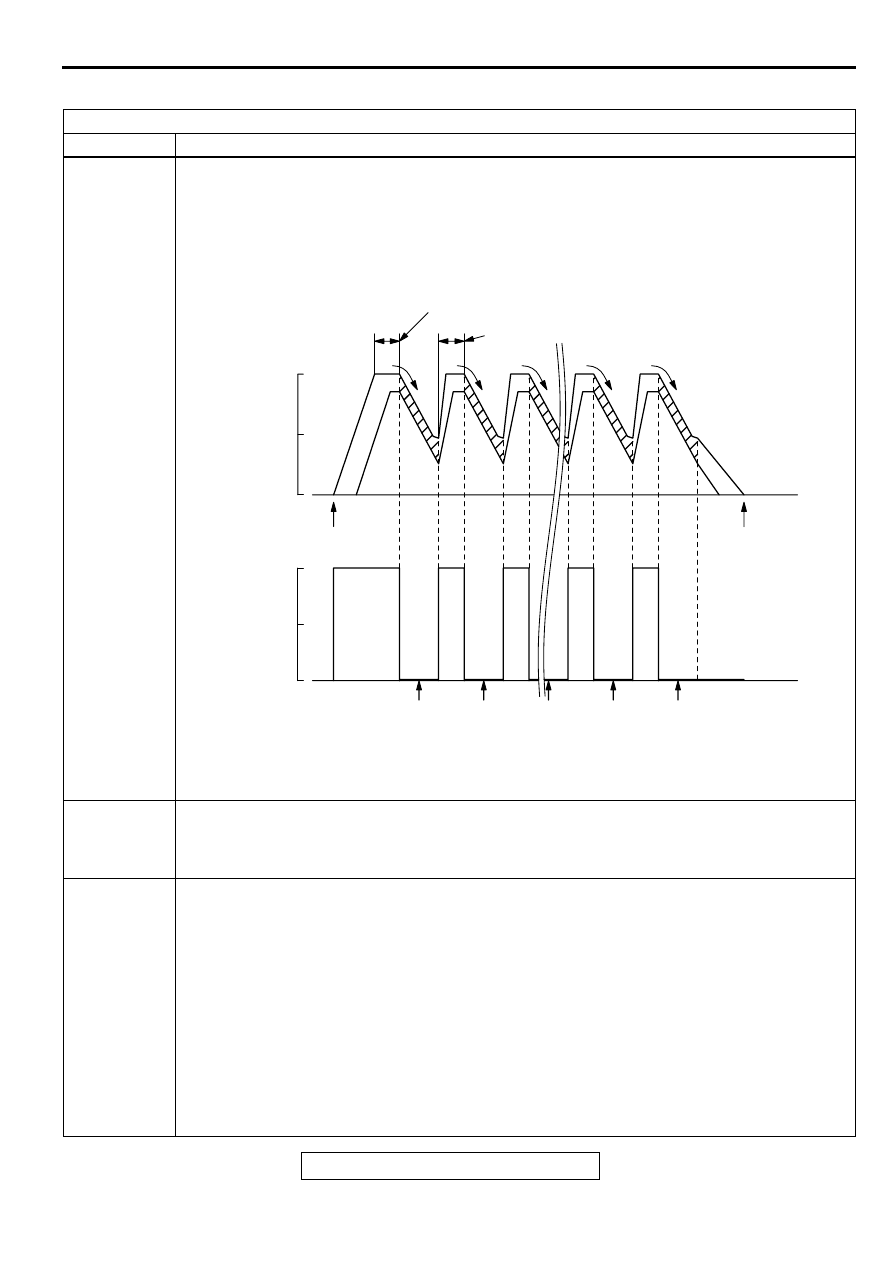
Drive cycle
pattern
This monitor [from start to ignition switch to the "LOCK" (OFF) position] will be completed while
traveling with the following drive cycle pattern. It will take 10 minutes. You must complete this drive
twice.
NOTE: . Vehicle speed and throttle opening angle should be within the shaded range.
Inspection
conditions
•
Engine coolant temperature: 80
°
C (176
°
F) or more
•
Atmospheric temperature: 5
°
C (41
°
F) or more
•
A/C switch: OFF
•
Condition of A/T: Selector lever D range
Test procedure
1. Engine: start
2. Accelerate until the vehicle speed is 56
−
64 km/h (35
−
40 mph).
3. Travel for 20 seconds or more while keeping the vehicle speed at 56
−
64 km/h (35 - 40 mph). (M/
T = 4th speed)
4. Fully close the throttle from an engine speed of 2,000
−
3,000 r/min, and decelerate to approx. 900
r/min without applying the brakes. Do not steer the handle or turn the light ON/OFF during this
time. (During monitor)
5. Accelerate until the vehicle speed reaches 56
−
64 km/h (35
−
40 mph), and travel for 20 seconds
or more. Then, repeat steps 4 and 5 and complete 8 monitor sessions.
6. Return the vehicle to the shop, then turn the ignition switch to the "LOCK" (OFF) position.
7. Confirm that the diagnostic trouble code (DTC) is not output.
8. If DTC P0401 is output, refer to, DTC P0401
−
Exhaust Gas Recirculation Flow Insufficient
Detected.
AKX01349
(2)
AKX01349
(3)
(5)
(5)
(5)
(5)
(2)
(1)
(4)
(4)
(4)
(4)
(4)
20 SECONDS OR MORE
56 - 64 km/h (35 - 40 mph)
M/T: 4TH SPEED
20 SECONDS OR MORE
1 ST
MON-
ITOR
7 TH
MON-
ITOR
8 TH
MON-
ITOR
2 ND
MON-
ITOR
ENGINE START
IGNITION
SWITCH:"LOCK"
(OFF) position
FULL
DECEL-
ERATION
FULL
DECEL-
ERATION
FULL
DECEL-
ERATION
FULL
DECEL-
ERATION
FULL
DECEL-
ERATION
64
(40)
32
(20)
0
100
50
0
VEHICLE
SPEED
km/h (mph)
CALCULATED
LOAD (%)
AKX01349AC
MULTIPORT FUEL INJECTION (MFI) DIAGNOSIS
TSB Revision
MULTIPORT FUEL INJECTION (MFI) <3.0L ENGINE>
13B-16
PROCEDURE 6
OTHER MONITOR (Main components, sensors and switches, wire breakage and short circuit)
DTC
•
Main components: P0134, P0154,P0300, P0301, P0302, P0303, P0304, P0305, P0306, P0506,P0507,P1400
•
Sensors and switches: P0101,P0102,P0103,P0107,P0108,P0111,P0115,P0116,P0117, P0121,P0122,P0123,
P0335, P0340, P0551
•
Wire breakage and short circuit: P0130, P0135, P0136, P0141, P0150, P0155, P0156, P0161, P0201, P0202,
P0203, P0204, P0205, P0206, P0403, P0443, P0446, P1500
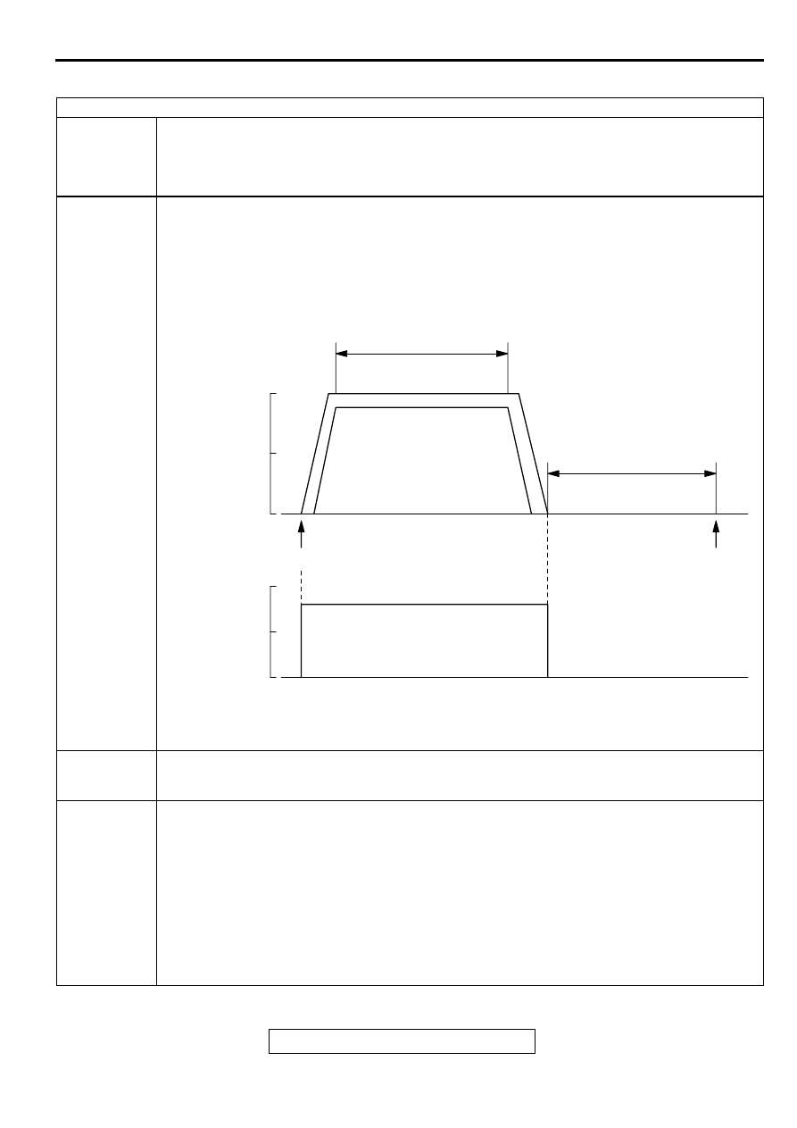
Drive cycle
pattern
This monitor [from start to ignition switch to the "LOCK" (OFF) position] will be completed while traveling with the
following drive cycle pattern. It will take 10 minutes. You must complete this drive twice.
NOTE: . Drive according to the graph below.
Inspection
conditions
•
Engine coolant temperature: 80
°
C (176
°
F) or more
•
Atmospheric temperature: 5
°
C (41
°
F) or more
•
Condition of A/T: Selector lever D range
Test procedure
Engine: start
Accelerate until the vehicle speed is 56
−
64 km/h (35
−
40 mph), and travel for 300 seconds or more. (M/T = 4th
speed)
Return the vehicle to the shop.
After stopping the vehicle, continue idling for 300 seconds, and then turn the ignition switch to the "LOCK" (OFF)
position. Moreover, the vehicle should be set to the following conditions for idling.
•
A/C switch: OFF
•
Lights and all accessories: OFF
•
Transaxle: P range
•
Steering wheel: Straightforward position
Confirm that the diagnostic trouble code (DTC) is not output.
If a DTC is output, refer to Diagnostic Trouble Code Chart.
.
AKX01350
AKX01350
(3)
(2)
(1)
(4)
300 SECONDS OR MORE
56 - 64 km/h (35 - 40 mph)
M/T: 4TH SPEED
ENGINE: IDLING
TRANSMISSION: NEUTRAL
300 SECONDS
ENGINE START
IGNITION
SWITCH:"LOCK"
(OFF) position
64
(40)
32
(20)
0
100
50
0
VEHICLE
SPEED
km/h (mph)
CALCULATED
LOAD (%)
AKX01350 AC

MULTIPORT FUEL INJECTION (MFI) DIAGNOSIS
TSB Revision
MULTIPORT FUEL INJECTION (MFI) <3.0L ENGINE>
13B-17
READINESS TEST STATUS
Purpose
The Readiness function also referred as I/M
Readiness or I/M Flags indicate if a full diagnostic
check has been "Completed" (is "Ready") for each
non-continuous monitor. Enhanced I/M State
Emission Programs will use the Readiness status
(Codes) to see if the vehicle is ready for OBD II
testing. "Incomplete" (Not Ready) codes will be one
of the triggers for I/M failure.
Overview
The engine control module (ECM) <M/T> or
powertrain control module (PCM) <A/T> monitors the
following main diagnosis items and records whether
the evaluation was completed or is incomplete. The
Readiness codes were established for the I/M
programs, thereby confirming that the vehicle was
not tampered with by erasing the DTC's before I/M
testing. The Readiness and DTC codes can be reset
by disconnecting the battery or by erasing the codes
with a scan tool. For this reason all Readiness codes
must read "Complete" before I/M testing. When the
monitors run and complete, the MUT II will record the
Readiness Code as "Complete" (General Scan Tools
record as "Ready"). If the monitor did not run
completely, the system then reads as "Incomplete"
(General Scan Tools record as "Not Ready").
When the monitors run and complete, the MUT II will
record the Readiness Code as "Complete" (General
Scan Tools record as "Ready"). If the monitor did not
run completely, the system then reads as
"Incomplete" (General Scan Tools record as "Not
Ready"). When the vehicle is operating normally and
the OBD II Drive Cycle is carried out, Readiness
Code will set as "Complete" on the first drive cycle. If
during the first drive cycle a fault is detected then, a
second drive is required before the Readiness Code
will "Complete." If the fault is still there, then a DTC
will set.
•
Catalyst: P0421, P0431
•
Evaporative system: P0442, P0455
•
Heated oxygen sensor:
P0130,P0133,P0136,P0139,P0150,P0153,P015
6,P0159
•
Heated oxygen sensor heater: P0135, P0141,
P0155, P0161
•
EGR system: P0401
After the Readiness is "Complete," the technician is
assured that any DTC's associated with that monitor
will be displayed if the system has a problem. That is
why some State's I/M programs require the
Readiness Code as "Complete" before they check
for DTC's.
NOTE: After a repair is mode for a DTC the
technician should drive the OBD II drive cycle
checking that the MUT II records all Readiness as
"Complete".
FAIL-SAFE/BACKUP FUNCTION TABLE
M1131009100065
When the main sensor malfunctions are detected by the diagnostic test mode, the vehicle is controlled by
means of the following defaults.
MALFUNCTION ITEM
CONTROL CONTENTS DURING MALFUNCTION
Volume air flow sensor
1. Uses the throttle position sensor signal and engine speed signal (crankshaft
position sensor signal) for basic injector drive time and basic ignition timing
from the pre-set mapping.
2. Fixes the IAC motor in the appointed position so idle air control is not
performed.
Intake air temperature
sensor
Controls as if the intake air temperature is 25
°
C (77
°
F).
Throttle position sensor
No increase in fuel injection amount during acceleration due to the unreliable
throttle position sensor signal.
Engine coolant
temperature sensor
Controls as if the engine coolant temperature is 80
°
C (176
°
F). (This control will
be continued until the ignition switch is turned to the "LOCK" (OFF) position
even though the sensor signal returns to normal.)
Camshaft position sensor Injects fuel simultaneously into all cylinders. (After the ignition switch is turned to
the "ON" position, the No.1 cylinder top dead center is not detected at all.)
Barometric pressure
sensor
Controls as if the barometric pressure is 101 kPa (30 in Hg).
MULTIPORT FUEL INJECTION (MFI) DIAGNOSIS
TSB Revision
MULTIPORT FUEL INJECTION (MFI) <3.0L ENGINE>
13B-18
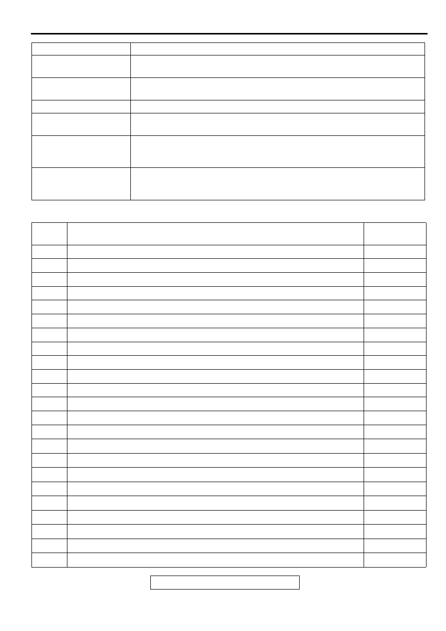
DIAGNOSTIC TROUBLE CODE CHART
M1131008700086
Knock sensor
Switches the ignition timing from ignition timing for high octane to ignition timing
for standard octane fuel.
Communication line with
transaxle control CPU
No ignition timing retard control (overall engine-transaxle control) achieved
when transaxle speeds are changed.
Generator FR terminal
Does not restrict the generator output with respect to electrical load.
Heated oxygen sensor
<front>
Air/fuel ratio closed loop control is not performed.
Heated oxygen sensor
<rear>
Performs the closed loop control of the air/fuel ratio by using only the signal of
the heated oxygen sensor (front) installed on the front side of the catalytic
converter.
Misfire detection
The ECM <M/T> or PCM <A/T> stops supplying fuel to the cylinder with the
highest misfiring rate if a misfiring that could damage the catalytic converter is
detected.
MALFUNCTION ITEM
CONTROL CONTENTS DURING MALFUNCTION
DTC
CODE
DIAGNOSTIC ITEMS
REFERENCE
PAGE
P0101
Volume air flow circuit range/performance problem
P0102
Volume air flow circuit low input
P0103
Volume air flow circuit high input
P0107
Barometric pressure circuit low input
P0108
Barometric pressure circuit high input
P0111
Intake air temperature circuit range/performance problem
P0115
Engine coolant temperature circuit high input
P0116
Engine coolant temperature circuit range/performance problem
P0117
Engine coolant temperature circuit low input
P0121
Throttle position circuit range/performance problem
P0122
Throttle position circuit low input
P0123
Throttle position circuit high input
P0128
Coolant thermostat malfunction
P0130
O
2
Sensor circuit malfunction (bank 1 sensor 1)
P0133
O
2
Sensor circuit slow response (bank 1 sensor 1)
P0134
O
2
Sensor circuit no activity detected (bank 1 sensor 1)
P0135
O
2
Sensor heater circuit malfunction (bank 1 sensor 1)
P0136
O
2
Sensor circuit malfunction (bank 1 sensor 2)
P0139O
2
Sensor circuit slow response (bank 1 sensor 2)
P0141
O
2
Sensor heater circuit malfunction (bank 1 sensor 2)
P0150
O
2
Sensor circuit malfunction (bank 2 sensor 1)
P0153
O
2
Sensor circuit slow response (bank 2 sensor 1)
P0154
O
2
Sensor circuit no activity detected (bank 2 sensor 1)
Нет комментариевНе стесняйтесь поделиться с нами вашим ценным мнением.
Текст