Mitsubishi Eclipse / Eclipse Spyder (2000-2002). Service and repair manual — part 207
MULTIPORT FUEL INJECTION (MFI) DIAGNOSIS
TSB Revision
MULTIPORT FUEL INJECTION (MFI) <3.0L ENGINE>
13B-27
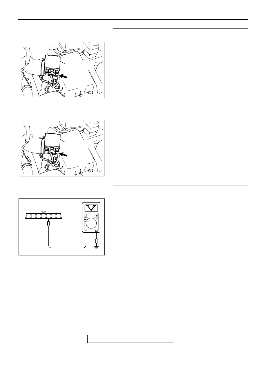
STEP 4. Check connector B-14 at the volume air flow
sensor for damage.
Q: Is the connector in good condition?
YES : Repair harness wire between MFI relay connector A-
21X terminal 1 and volume air flow sensor connector
B-14 terminal 4 because of harness damage. Then go
to Step 13.
NO : Repair or replace it. Refer to GROUP 00E, Harness
Connector Inspection (
). Then go to Step 13.
STEP 5. Check connector B-14 at volume air flow sensor
for damage.
Q: Is the connector in good condition?
YES : Go to Step 6.
NO : Repair or replace it. Refer to GROUP 00E, Harness
Connector Inspection (
). Then go to Step 13.
STEP 6. Check the sensor supply voltage at volume air
flow sensor harness side connector B-14.
(1) Disconnect the connector B-14 and measure at the harness
side.
(2) Turn the ignition switch to the "ON" position.
(3) Measure the voltage between terminal 3 and ground.
•
Voltage should be between 4.8 and 5.2 volts.
(4) Turn the ignition switch to the "LOCK" (OFF) position.
Q: Is the voltage normal?
YES : Go to Step 9.
NO : Go to Step 7.
ACX02480
CONNECTOR : B-14
AC
VOLUME AIR
FLOW SENSOR
ACX02480
CONNECTOR : B-14
AC
VOLUME AIR
FLOW SENSOR
AKX01406 AC
B-14 HARNESS
SIDE CONNECTOR
7 6 5 4 3 2 1
MULTIPORT FUEL INJECTION (MFI) DIAGNOSIS
TSB Revision
MULTIPORT FUEL INJECTION (MFI) <3.0L ENGINE>
13B-28
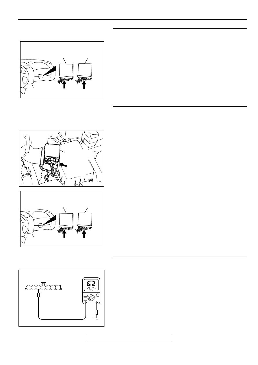
STEP 7. Check connector C-58 at ECM <M/T> or connector
C-55 at PCM <A/T> for damage.
Q: Is the harness connector in good condition?
YES : Go to Step 8.
NO : Repair or replace it. Refer to GROUP 00E, Harness
Connector Inspection (
). Then go to Step 13.
STEP 8. Check for short circuit to ground between volume
air flow sensor connector B-14 terminal 3 and ECM
connector C-58 terminal 61 <M/T> or PCM connector C-55
terminal 65 <A/T>.
Q: Is the harness wire in good condition?
YES : Replace the ECM or PCM. Then go to Step 13.
NO : Repair it. Then go to Step 13.
STEP 9. Check the continuity at volume air flow sensor
harness side connector B-14.
(1) Disconnect the connector B-14 and measure at the harness
side.
(2) Check for the continuity between terminal 5 and ground.
•
Should be less than 2 ohm.
Q: Is the continuity normal?
YES : Go to Step 12.
NO : Go to Step 10.
AK000225
CONNECTOR : C-58<M/T>, C-55<A/T>
C-55
C-58
PCM<A/T>
ECM<M/T>
AI
ACX02480
CONNECTOR : B-14
AC
VOLUME AIR
FLOW SENSOR
AK000225
CONNECTOR : C-58<M/T>, C-55<A/T>
C-55
C-58
PCM<A/T>
ECM<M/T>
AI
AKX01409AC
B-14 HARNESS
SIDE CONNECTOR
7 6 5 4 3 2 1
MULTIPORT FUEL INJECTION (MFI) DIAGNOSIS
TSB Revision
MULTIPORT FUEL INJECTION (MFI) <3.0L ENGINE>
13B-29
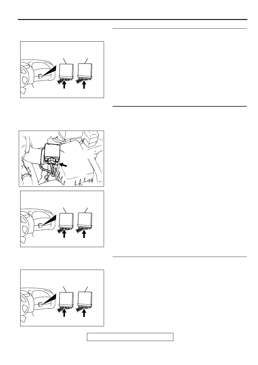
STEP 10. Check connector C-58 at ECM <M/T> or
connector C-55 at PCM <A/T> for damage.
Q: Is the connector in good condition?
YES : Go to Step 11.
NO : Repair or replace it. Refer to GROUP 00E, Harness
Connector Inspection (
). Then go to Step 13.
STEP 11. Check for open circuit and harness damage
between volume air flow sensor connector B-14 terminal 5
and ECM connector C-58 terminal 49 <M/T> or PCM
connector C-55 terminal 57 <A/T>.
Q: Is the harness wire in good condition?
YES : Replace the ECM or PCM. Then go to Step 13.
NO : Repair it. Then go to Step 13.
STEP 12. Check connector C-58 at ECM <M/T> or
connector C-55 at PCM <A/T> for damage.
Q: Is the connector in good condition?
YES : Replace the volume air flow sensor. Then go to Step
13.
NO : Repair or replace it. Refer to GROUP 00E, Harness
Connector Inspection (
). Then go to Step 13.
AK000225
CONNECTOR : C-58<M/T>, C-55<A/T>
C-55
C-58
PCM<A/T>
ECM<M/T>
AI
ACX02480
CONNECTOR : B-14
AC
VOLUME AIR
FLOW SENSOR
AK000225
CONNECTOR : C-58<M/T>, C-55<A/T>
C-55
C-58
PCM<A/T>
ECM<M/T>
AI
AK000225
CONNECTOR : C-58<M/T>, C-55<A/T>
C-55
C-58
PCM<A/T>
ECM<M/T>
AI
MULTIPORT FUEL INJECTION (MFI) DIAGNOSIS
TSB Revision
MULTIPORT FUEL INJECTION (MFI) <3.0L ENGINE>
13B-30
STEP 13. Test the OBD-II drive cycle.
(1) Carry out a test drive with the drive cycle pattern. Refer to
, Procedure 6
−
Other Monitor.
(2) Check the diagnostic trouble code (DTC).
Q: Is the DTC P0101 is output?
YES : Retry the troubleshooting.
NO : The inspection is complete.
Нет комментариевНе стесняйтесь поделиться с нами вашим ценным мнением.
Текст