Mitsubishi Colt Ralliart. Manual — part 672
TROUBLESHOOTING
MULTIPORT FUEL INJECTION (MPI) <4G1>
13B-13
Procedure 1
Catalytic converter monitor
Diagnosis
code No.
P0421
Drive cycle
pattern
One trip monitor [from start to ignition switch to "LOCK" (OFF) position] will be completed
while traveling with the following drive cycle pattern. It will take 16 minutes or more.
Inspection
condition
• Atmospheric temperature: −10°C or more
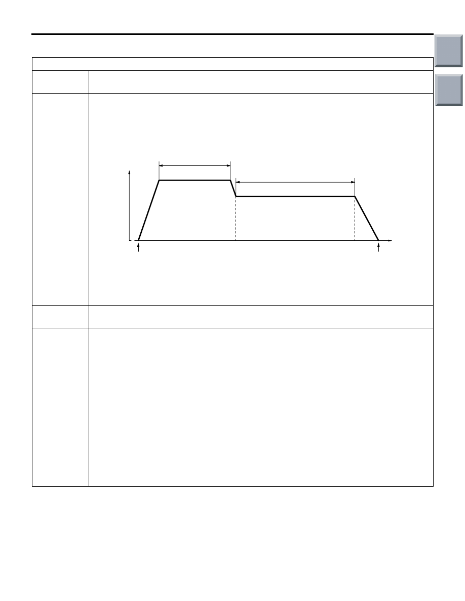
Test
procedure
1. Engine: start
2. Accelerate until the vehicle speed is 90 km/h or more.
3. Travel for 6 minutes or more while keeping the vehicle speed at 90 km/h or more.
4. Decelerate until the vehicle speed is within 80 km/h or less.
5. While traveling at 55
− 80 km/h for 10 minutes or more, fully close the throttle at least once
in 2 minutes and decelerate for 10 seconds or more.
• Do not repeat deceleration too often.
• Vehicle speed may go below 55 km/h after the deceleration.
• Stopping and braking are permitted. (If stopped or drive at 55 km/h or less for more
than 5 minutes the monitoring may be stopped. In this case please restart monitoring
from the beginning.)
6. After completing the above deceleration, bring the vehicle speed back to 55
− 80 km/h and
keep it in the range until starting the deceleration again.
• Repeat the above deceleration at least 5 times.
7. Return the vehicle to the shop, then turn the ignition switch to "LOCK" (OFF) position.
AK301815
10 minutes or more
Ignition switch :
"LOCK" (OFF)
position
Engine Start
Vehicle
speed
6 minutes or more
90 km/h or more
55 - 80 km/h
(1)
(5,6)
(4)
(3)
(2)
(7)
Time
Stopping and braking
permitted
AB
Main
Index
Group
TOC

TROUBLESHOOTING
MULTIPORT FUEL INJECTION (MPI) <4G1>
13B-14
Procedure 2
Oxygen sensor (front) monitor
Diagnosis
code No.
P0130
Drive cycle
pattern
One trip monitor [from start to ignition switch to "LOCK" (OFF) position] will be completed
while traveling with the following drive cycle pattern. It will take 16 minutes or more.
Inspection
conditions
• Engine coolant temperature: After engine warm up
• Atmospheric temperature: −10°C or more
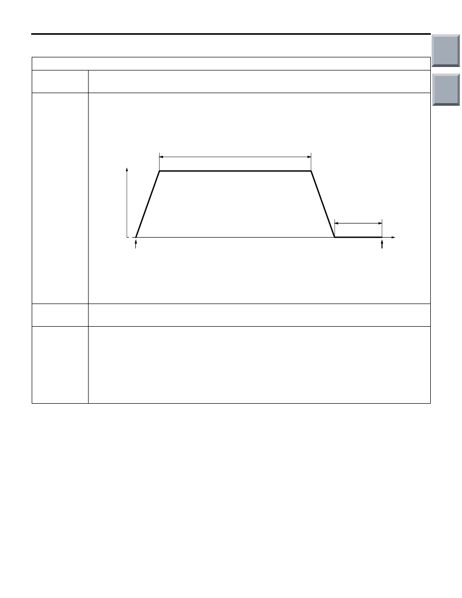
Test
procedure
1. Engine: start
2. Accelerate until the vehicle speed is 55
− 80 km/h.
3. While keeping the accelerator pedal opening degree constant, keep the vehicle speed at
55
− 80km/h and travel for 16 minutes or more.
• Stopping and braking during this operation are permitted.
4. Return the vehicle to the shop, then turn the ignition switch to "LOCK" (OFF) position.
AK301816AB
16 minutes or more
Ignition switch :
"LOCK" (OFF)
position
Engine Start
Vehicle
speed
55 - 80 km/h
(1)
(4)
(3)
(2)
Time
Stopping and braking
permitted
Main
Index
Group
TOC
TROUBLESHOOTING
MULTIPORT FUEL INJECTION (MPI) <4G1>
13B-15
Procedure 3
Other monitor
Diagnosis
code No.
P0135, P0136, P0141, P0300, P0301, P0302, P0303, P0304, P0325, P0500, P0638
Drive cycle
pattern
One trip monitor [from start to ignition switch to "LOCK" (OFF) position] will be completed
while traveling with the following drive cycle pattern. It will take 21 minutes or more.
Inspection
conditions
• Engine coolant temperature: After engine warm up
• Atmospheric temperature: −10°C or more
Test
procedure
1. Engine: start
2. Accelerate until the vehicle speed is 55 km/h.
3. While keeping the accelerator pedal opening degree constant, keep the vehicle speed at
55 km/h and travel for 16 minutes or more.
4. Return the vehicle to the shop.
5. After stopping the vehicle, continue idling for 5 minutes, and then turn the ignition switch
to "LOCK" (OFF) position.
AK301817
16 minutes or more
Ignition switch :
"LOCK" (OFF)
position
Engine Start
Vehicle
speed
55 km/h or more
(1)
(4)
(3)
(2)
(5)
Time
AB
5 minutes or more
Engine: Idling
Transmission: Neutral
Main
Index
Group
TOC

TROUBLESHOOTING
MULTIPORT FUEL INJECTION (MPI) <4G1>
13B-16
FAIL-SAFE/BACKUP FUNCTION
When the diagnosis function detects a malfunction in
any of the main sensors, the fail-safe/backup func-
tion enables the vehicle to still be driven safely by
using one of the pre-established control logics appro-
priate for the malfunctioning sensor.
CONTROL DETAILS BY FAIL-SAFE/BACKUP FUNCTION
Malfunctioning item Control detail
Air flow sensor
1. Based on the throttle position sensor signal data and the crank angle sensor
signal data (engine speed data), the ECU determines the basic injector
activation time and basic ignition timing from a pre-established map.
2. The ECU does not control the idling speed.
Intake air temperature
sensor
The ECU performs control assuming a 25
°C intake air temperature.
Engine coolant
temperature sensor
The ECU performs control assuming a 80
°C engine coolant temperature. (This
control persists until the ignition switch is turned to the "LOCK" (OFF) position
even after the engine coolant sensor starts re-supplying normal signals.)
Oxygen sensor
<front>
Air/fuel ratio closed loop control is not performed.
Oxygen sensor
<rear>
Per forms the closed loop control of the air/fuel ratio by using only the signal of
the oxygen sensor (front) installed on the front side of the catalytic converter.
Throttle position
sensor (main)
• The ECU controls the throttle valve position using signals from the throttle
position sensor (sub).
• The ECU assumes the accelerator position to be at an approximately
half-stroke position.
• Engine speed feedback control is prohibited.
• The ECU cuts off fuel supply when the engine speed exceeds 3,000 r/min.
• When the throttle position sensor (sub) is also malfunctioning, the ECU
deactivates the electronic-controlled throttle valve system and limits the
engine output to a certain low level.
Accelerator pedal
position sensor
(main)
• The ECU determines the accelerator pedal position using the signals from
the accelerator pedal position sensor (sub). However, the pedal stroke
position thus determined is interpreted as approximately a half of the normal
state position.
• The ECU cuts off fuel supply when the engine speed exceeds 3,000 r/min.
• When the accelerator pedal position sensor (sub) is also malfunctioning, the
ECU deactivates the electronic-controlled throttle valve system and limits the
engine output to a certain low level.
Throttle position
sensor (sub)
• The ECU controls the throttle valve position using signals from the throttle
position sensor (main).
• The ECU assumes the accelerator position to be an approximately
half-stroke position.
• The ECU cuts off fuel supply when the engine speed exceeds 3,000 r/min.
• When the throttle position sensor (main) is also malfunctioning, the ECU
deactivates the electronic-controlled throttle valve system and limits the
engine output to a certain low level.
Ignition coil (power
transistor)
The ECU stops fuel injection into the cylinder with abnormal ignition.
Detonation sensor
The ECU fixes the ignition timing to a one safe enough against detonation.
Main
Index
Group
TOC
Нет комментариевНе стесняйтесь поделиться с нами вашим ценным мнением.
Текст