Mitsubishi Colt Ralliart. Manual — part 671
TROUBLESHOOTING
MULTIPORT FUEL INJECTION (MPI) <4G1>
13B-9
TROUBLESHOOTING
DIAGNOSIS TROUBLESHOOTING FLOW
M1131150001367
Refer to
, GROUP 00
− How to Use Trouble-
shooting/Inspection Service Points
− How to Cope
with Intermittent Malfunctions.
DIAGNOSIS FUNCTION
M1131155501851
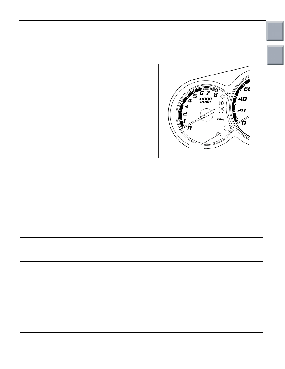
ENGINE WARNING LAMP (CHECK
ENGINE LAMP)
The engine warning lamp illuminates in the event of
an abnormality in any of the diagnosis items related
to the Multipoint Fuel Injection (MPI) system listed
below. Check diagnosis code outputs both when the
lamp stays illuminated and when it lights up or
flashes while the engine is running. Even when there
is no problem, the lamp is caused to illuminate for
about 5 seconds after turning the ignition switch to
the ON position for the blown bulb checking pur-
poses.
ENGINE WARNING LAMP INSPECTION ITEMS
AK402082AD
Engine
warning lamp
Code No.
Diagnosis item
P0090
Fuel pressure solenoid valve system
P0100
Airflow sensor system
P0105
Barometric pressure sensor system
P0110
Intake air temperature sensor system
P0115
Engine coolant temperature sensor system
P0122
Throttle position sensor (main) circuit low input
P0123
Throttle position sensor (main) circuit high input
P0125
Feedback system monitor
P0130
Oxygen sensor (front) system
P0135
Oxygen sensor (front) heater system
P0136
Oxygen sensor (rear) system
P0141
Oxygen sensor heater (rear) system
P0170
Abnormal fuel system
P0201
No. 1 injector system
Main
Index
Group
TOC

TROUBLESHOOTING
MULTIPORT FUEL INJECTION (MPI) <4G1>
13B-10
P0202
No. 2 injector system
P0203
No. 3 injector system
P0204
No. 4 injector system
P0222
Throttle position sensor (sub) circuit low input
P0223
Throttle position sensor (sub) circuit high input
P0243
Waste gate solenoid valve system
P0300
Random/multiple cylinder misfire detected
P0301
No. 1 cylinder misfire detected
P0302
No. 2 cylinder misfire detected
P0303
No. 3 cylinder misfire detected
P0304
No. 4 cylinder misfire detected
P0325
Detonation sensor system
P0335
Crank angle sensor system
P0340
Camshaft position sensor system
P0421
Warm up catalyst malfunction
P0443
Purge control solenoid valve system
P0500
Vehicle speed sensor system
P0606
Microcomputer malfunction
P0638
Throttle valve control servo circuit range/performance problem
P0642
Throttle position sensor power supply
P0657
Throttle valve control servo relay circuit malfunction
P1021
Oil feeder control valve system
P1233
Trustful check throttle position sensor (main)
P1234
Trustful check throttle position sensor (sub)
P1235
Trustful check air flow sensor
P1236
A/D converter system
P1237
Trustful check accelerator pedal position sensor
P1238
Air flow sensor trustful for torque monitoring
P1239
Trustful check engine speed
P1241
Torque monitoring
P1602
Communication malfunction (btween engine-ECU main processor and system LSI)
P1603
Battery backup circuit malfunction
P2100
Throttle valve control servo circuit (open)
P2101
Throttle valve control servo magneto malfunction
P2108
Throttle valve control servo processor malfunction
P2122
Accelerator pedal position sensor (main) circuit low input
P2123
Accelerator pedal position sensor (main) circuit high input
P2127
Accelerator pedal position sensor (sub) circuit low input
P2128
Accelerator pedal position sensor (sub) circuit high input
Code No.
Diagnosis item
Main
Index
Group
TOC

TROUBLESHOOTING
MULTIPORT FUEL INJECTION (MPI) <4G1>
13B-11
CAUTION
The engine warning lamp illuminates steadily if
any abnormality has occurred in the engine-ECU.
NOTE: The engine warning lamp flashes if the electronically controlled throttle valve system is forced to stop
by activation of the fail-safe function.
METHOD FOR READING AND ERASING
DIAGNOSIS CODES
Refer to GROUP 00 – How to Use Troubleshoot-
ing/Inspection Service Points – How to Cope with
Intermittent Malfunctions
.
DIAGNOSIS USING INCREASED SENSI-
TIVITY DIAGNOSIS MODE
When the increased sensitivity diagnosis mode is
selected on the M.U.T.-III, the engine-ECU shifts into
the mode in which it causes the engine warning lamp
to light and stores the relevant diagnosis code imme-
diately after detection of a malfunction. Since this
mode allows the ECU to determine and store the
diagnosis code with a shorter delay time after detec-
tion of a malfunction (1 second instead of standard 4
seconds), it helps to reduce workload required for
fault condition identification and post-repair checking
operations. To revert from the increased sensitivity
diagnosis mode to the standard sensitivity diagnosis
mode, the ignition switch must be turned to the
"LOCK" (OFF) position or the standard sensitivity
mode must be re-selected on the M.U.T.-III. The
diagnosis code and the freeze-frame data retained in
memory during the increased sensitivity diagnosis
mode must, if necessary, be recorded before per-
forming the mode switching operation because they
will be automatically erased as soon as the standard
sensitivity diagnosis mode is re-selected.
Diagnosis Procedure
1. Connect the M.U.T.-III to the vehicle connector,
set the engine-ECU diagnosis mode to the
increased sensitivity diagnosis mode, and per-
form a road test.
2. Read diagnosis code(s) and repair the faulty
location(s).
3. Either re-select the standard sensitivity diagnosis
mode on the M.U.T.-III or turn the ignition switch
to the "LOCK" (OFF) position and then back to
the ON position.
NOTE: Turning the ignition switch to the "LOCK"
(OFF) position has the effect of causing the
engine-ECU to switch its diagnosis mode from
the increased sensitivity diagnosis mode to the
standard sensitivity diagnosis mode.
INSPECTION USING M.U.T.-III DATA LIST
AND ACTUATOR TEST FUNCTIONS
Using the data list display function and actuator test
function of the M.U.T.-III, you can check vehicle har-
nesses and components for any abnormalities. The
data list display function allows inputs from sensors
and outputs to actuators both in numerical value and
graph formats. The actuator test function allows forc-
ing desired actuators to operate (turning on an actua-
tor and turning it off after predetermined period).
Diagnosis Procedure
1. Connect the M.U.T.-III to the vehicle connector
and carry out necessary inspections using the
data list function and/or actuator test function.
2. If any abnormality is found, inspect the relevant
vehicle harnesses or components and repair
them if necessary.
3. After the repair, check that the input/output levels
have returned to normal ranges levels.
4. Clear any diagnosis code that has resulted from
inspection and repair operations.
5. Disconnect the M.U.T.-III and perform a road test
or other necessary tests to confirm that there are
no problems remaining.
FREEZE FRAME DATA
When the engine-ECU detects a malfunction and
stores the corresponding diagnosis code, it also
stores the data showing the state of the engine at the
time of malfunction detection. These data are called
"freeze frame data". Analyzing the data using the
M.U.T.-III will help you to perform troubleshooting
efficiently.
NOTE: Freeze frame data are displayed in terms of
the items listed below.
P2135
Throttle position sensor (main and sub) range/performance problem
P2138
Accelerator pedal position sensor (main and sub) range/performance problem
U1108
Combination meter time-out
Code No.
Diagnosis item
Main
Index
Group
TOC

TROUBLESHOOTING
MULTIPORT FUEL INJECTION (MPI) <4G1>
13B-12
DATA DISPLAY ITEM LIST
NOTE:
*1
: A state in which fuel control is performed using oxygen sensor signals fed back to the engine-ECU.
NOTE:
*2
: A state in which the closed-loop conditions are not yet met, making the engine-ECU perform fuel
control without feedback data from the oxygen sensors.
NOTE:
*3
: A state in which open-loop control is needed due to repeated acceleration and deceleration.
NOTE:
*4
: A state in which open-loop control is performed in consequence of a system malfunction.
DRIVE CYCLE
The following three drive cycle patterns are performed on the diagnosis codes monitored during the vehicle
driving. The vehicle driving requires the patterns to identify the fault. In other words, doing such a drive allows
to regenerate any kind of trouble which involves illuminating the engine warming lamp (check engine lamp)
and to verify the repair procedure has eliminated the trouble [the engine warming lamp (check engine lamp) is
no longer illuminated].
CAUTION
Two technicians should always be in the vehicle when carrying out a test drive.
NOTE: Check that the diagnosis code is not output before traveling in the drive cycle pattern. Erase the diag-
nosis code if it has been output.
DRIVE CYCLE PATTERN LIST
Item No.
Data
Unit/state
12
Air flow sensor
g/sec
13
Intake air temperature sensor
°C
21
Engine coolant sensor
°C
22
Crank angle sensor
r/min
24
Vehicle speed
km/h
44
Ignition timing
deg
79
Throttle position sensor (main)
mV
81
Long-term fuel consumption
%
82
Short-term fuel consumption
%
87
Calculation load value
%
88
Fuel control condition
Closed loop
*1
CL
Open loop
*2
OL
Open loop owing to drive condition
*3
OL-DRV.
Open loop owing to system malfunction
*4
OL-SYS.
89
Fuel control condition
−
Procedure
Monitor item
Diagnosis code No.
Catalytic converter monitor
P0421
Oxygen sensor (front) monitor
P0130
Other monitor
P0135, P0136, P0141,
P0300, P0301, P0302,
P0303, P0304, P0325,
P0500, P0638
Main
Index
Group
TOC
Нет комментариевНе стесняйтесь поделиться с нами вашим ценным мнением.
Текст