Mitsubishi Colt Ralliart. Manual — part 575
POST-COLLISION DIAGNOSIS
SUPPLEMENTAL RESTRAINT SYSTEM (SRS)
52B-138
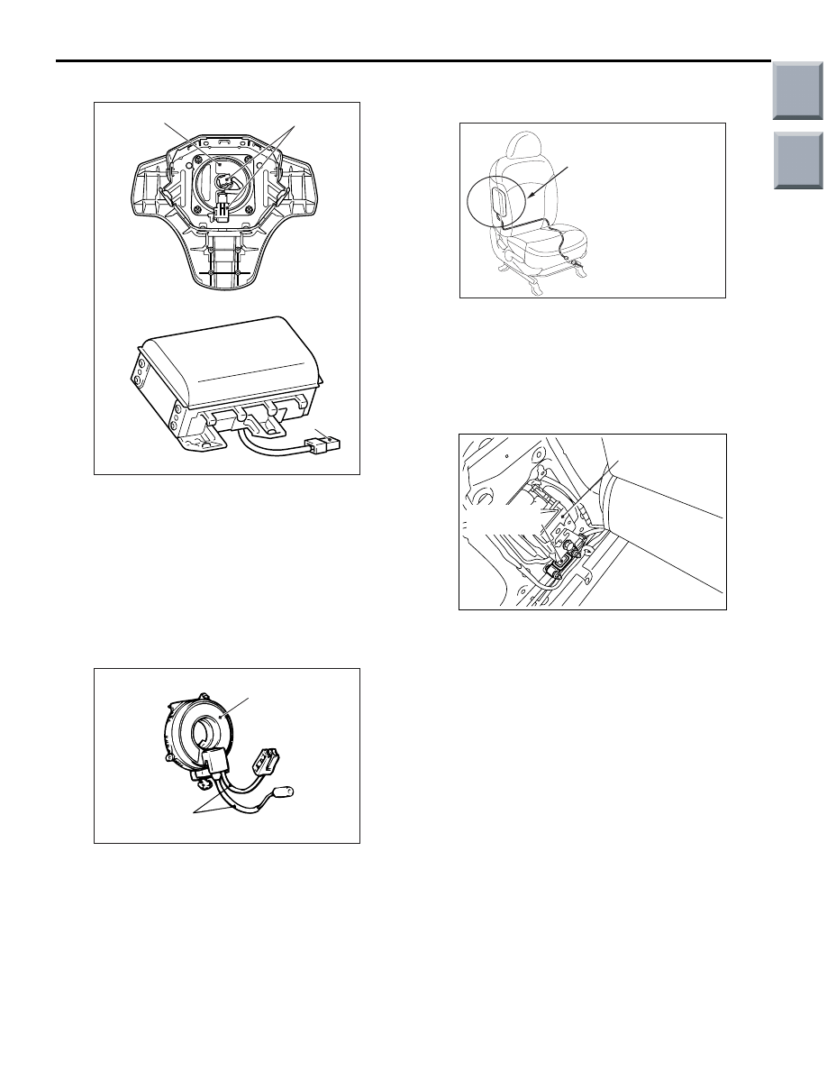
AIR BAG MODULES
1. Check the pad cover for dents, cracks or
deformation.
2. Check the connector for damage, terminals
deformities, and the harness for binding.
3. Check the air bag inflator case for dents, cracks or
deformities.
4. Check the air bag modules for proper installation.
CLOCK SPRING
1. Check the clock spring connectors and protective
tube for damage, and the terminals for
deformation.
2. Visually check the case for damage.
FRONT SEATBACK ASSEMBLY
(SIDE-AIRBAG MODULE)
1. Check the side-airbag module deployment section
in the seat for dents and deformation.
2. Check the connectors for damage, the terminals
for deformation, and the harness for binds.
SIDE IMPACT SENSOR
1. Check the centre pillar for deformation or rust.
2. Check the side impact sensors for dents, cracks,
deformation and rust.
3. Check the connector for damage and the
terminals for deformation.
NOTE: The figures show side impact sensors
(LH). The side impact sensors (RH) is symmetri-
cal with the side impact sensors (LH).
AC208717
Connector
Inflator case
Connector
AC
AC300585AD
Case
Protective tubes
AC208794AF
Side-airbag module
deployment section
AC311530
Side impact
sensor (front)
AC
Front seat belt
retractor
Main
Index
Group
TOC

INDIVIDUAL COMPONENT SERVICE
SUPPLEMENTAL RESTRAINT SYSTEM (SRS)
52B-139
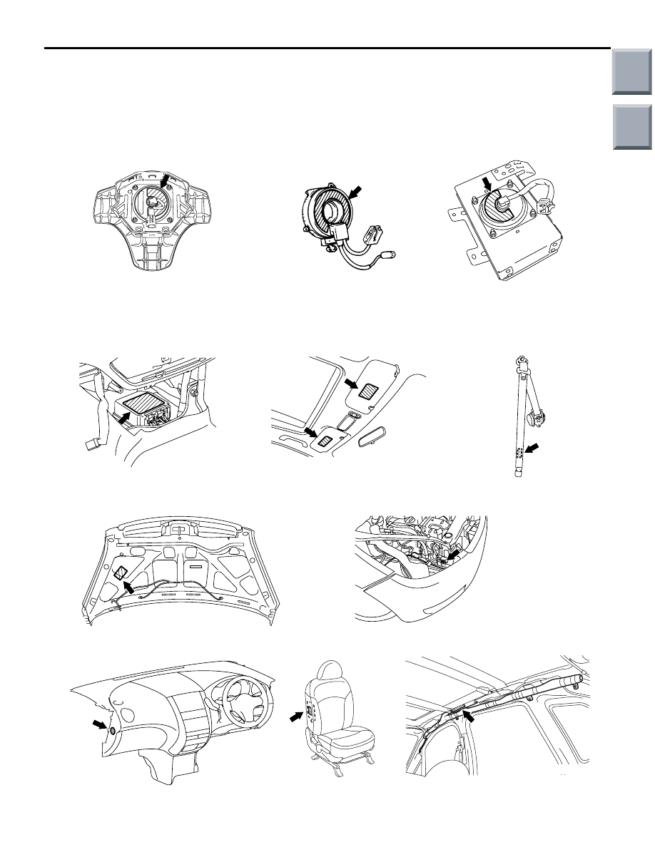
CURTAIN AIR BAG MODULES
1. Check that the curtain air bag deployment part of
the headlining is normal.
2. Check the inflator surface for cracks, dents or
deformations.
3. Check the air bag for breakage.
4. Check the connector for damage, the terminal for
deformation and the harness for binding.
STEERING WHEEL, STEERING COLUMN
AND SHAFT ASSEMBLY
1. Check the wiring harness (built into the steering
wheel) and the connectors for damage, and the
terminals for deformation.
2. Install the air bag module to check fit or alignment
with the steering wheel.
3. Check the steering wheel for noise, binding or
difficult operation and excessive free play.
4. Check the steering column shaft shock absorbing
mechanism (Refer to GROUP 37, On-Vehicle
Service
).
SEAT BELT WITH PRE-TENSIONER
1. Check the seat belt for damage or deformation.
2. Check the seat belt with pre-tensioner for cracks
or deformation.
3. Check that the unit is installed correctly to the
vehicle body.
HARNESS CONNECTOR (INSTRUMENT
PANEL WIRING HARNESS AND FLOOR
WIRING HARNESS, ROOF WIRING
HARNESS)
Check harnesses for binding, connectors for damage
and terminals for deformation (Refer to
).
INDIVIDUAL COMPONENT SERVICE
M1524002900538
WARNING
•
If heat damage may occur during paint work, remove the SRS-ECU, the air bag modules,
the clock spring, impact sensors and the seat belt with pre-tensioner.
•
SRS-ECU, air bag modules, clock spring and impact sensors: 93
°
C or more
•
Seat belt with pre-tensioner: 90
°
C or more
•
If the SRS components are removed for the purpose of check, sheet metal repair, painting,
etc., they should be stored in a clean, dry place until they are reinstalled.
If the SRS components are to be removed or
replaced as a result of maintenance, troubleshooting
etc., follow the service procedures that follow.
• Front impact sensors; refer to
• SRS-ECU; refer to
• Front air bag modules and clock spring; refer
• Side and curtain air bag modules; refer to
• Side impact sensors; refer to
• Seat belt with pre-tensioner; refer to
AC208936
Curtain air bag module
deployment section
AC
Main
Index
Group
TOC
WARNING/CAUTION LABELS
SUPPLEMENTAL RESTRAINT SYSTEM (SRS)
52B-140
WARNING/CAUTION LABELS
M1524003000549
Caution labels on the SRS are attached in the vehicle as shown. Follow label instructions when servicing the
SRS. If the label(s) are dirty or damaged, replace with new one(s).
AC510120
AC206616
AC206284
AC206096
AC206281
AC206097
AC400175
AC401506
AC207325
AC207330
AC402445
AC
Clock spring
Driver's air bag module
Passenger's (front)
air bag module
SRS-ECU
Sunvisor
Seat belt with pre-tensioner
(driver's and front passenger's seat)
Hood
Front impact sensor
Curtain air bag module
Side-airbag module
Instrument panel
Main
Index
Group
TOC

FRONT IMPACT SENSORS
SUPPLEMENTAL RESTRAINT SYSTEM (SRS)
52B-141
FRONT IMPACT SENSORS
REMOVAL AND INSTALLATION
M1524001500849
WARNING
•
Disconnect the negative battery terminal and wait for 60 seconds or more before starting
work. Furthermore, the disconnected battery terminal should be covered with tape to
insulate it.
•
Never attempt to disassemble or repair the front impact sensor. If faulty, replace it.
•
Do not drop or subject the front impact sensor to impact or vibration. If denting, cracking,
deformation, or rust are discovered in the front impact sensor, replace it with a new front
impact sensor. Discard the old one.
•
After deployment of an air bag, replace the front impact sensor with a new one.
NOTE: The figures show front impact sensor (LH).
Pre-removal Operation
• Turn the ignition key to the "LOCK" (OFF) position.
• Disconnect the Negative Battery Terminal.
AC207912
10 ± 2 N·m
1
AC
Headlamp support panel
Removal step
•
Headlamp (Refer to GROUP54,
Headlamp
).
1.
Front impact sensor
Installation steps
>>
A
<<
•
Pre-installation inspection
>>
B
<<
1.
Front impact sensor
•
Headlamp (Refer to GROUP54,
Headlamp
).
•
Negative battery cable connection
>>
C
•
Post-installation inspection
Installation steps (Continued)
Main
Index
Group
TOC
Нет комментариевНе стесняйтесь поделиться с нами вашим ценным мнением.
Текст