Mitsubishi Colt Ralliart. Manual — part 576
FRONT IMPACT SENSORS
SUPPLEMENTAL RESTRAINT SYSTEM (SRS)
52B-142
INSTALLATION SERVICE POINTS
>>A<< PRE-INSTALLATION INSPECTION
When the new front impact sensor refer to the previ-
ous item "INSPECTION."
>>B<< FRONT IMPACT SENSOR
INSTALLATION
WARNING
The SRS may not activate properly if a front
impact sensor is not installed properly.
1. Securely connect the connector.
2. Position the front impact sensor facing toward the
front of the vehicle as shown by the arrow on the
label, and install it securely.
>>C<< POST-INSTALLATION
INSPECTION
1. Connect the negative battery cable.
2. Turn the ignition key to "ON" position.
3. Does the "SRS" warning lamp illuminate for
approximately seven seconds, and go out?
4. If no, refer to troubleshooting (Refer to
INSPECTION
M1524001600620
WARNING
If a dent, crack, deformation or rust is
detected, replace with a new sensor.
1. Check the front impact sensor for dents, cracks,
deformation or rust.
2. Check the connector for damage, and terminals
for deformation.
3. Check the headlamp support panel for
deformation.
AC510172
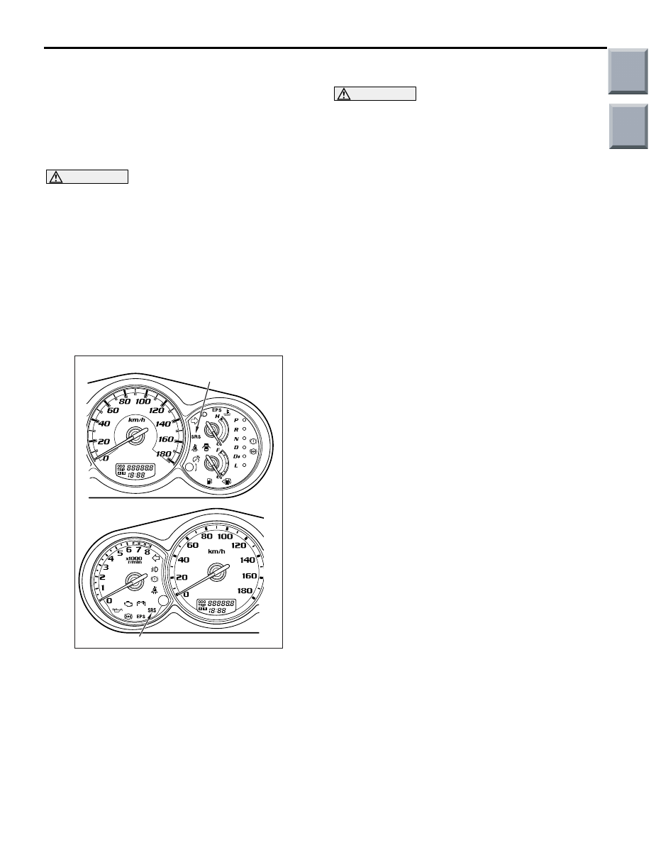
<VR-X>
<Except-VR-X>
SRS warning lamp
SRS warning lamp
AC
Main
Index
Group
TOC

SRS CONTROL UNIT (SRS-ECU)
SUPPLEMENTAL RESTRAINT SYSTEM (SRS)
52B-143
SRS CONTROL UNIT (SRS-ECU)
REMOVAL AND INSTALLATION
M1524002100963
WARNING
•
Disconnect the negative battery terminal and wait for 60 seconds or more before starting
work. Furthermore, the disconnected battery terminal should be covered with tape to
insulate it.
•
Never attempt to disassemble or repair the SRS-ECU. If faulty, replace it.
•
Do not drop or subject the SRS-ECU to impact or vibration. If denting, cracking, deforma-
tion, or rust are discovered in the SRS-ECU, replace it with a new front impact sensor. Dis-
card the old one.
•
After deployment of an air bag, replace the SRS-ECU with a new one.
•
Never use an ohmmeter on or near the SRS-ECU, and use only the special test equipment
described on
.
Pre-removal Operation
• Turn the ignition switch to the "LOCK" (OFF) position.
• Disconnect the Negative Battery Terminal.
AC207865
1
4.9 ± 0.98 N·m
AC
Removal steps
•
Centre console (Refer to GROUP
52A, Instrument panel assembly
).
1.
SRS-ECU
Installation steps
>>
A
1.
SRS-ECU
•
Centre console (Refer to GROUP
52A, Instrument panel assembly
).
•
Negative battery cable connection
>>
B
•
Post-installation inspection
Main
Index
Group
TOC

SRS CONTROL UNIT (SRS-ECU)
SUPPLEMENTAL RESTRAINT SYSTEM (SRS)
52B-144
INSTALLATION SERVICE POINTS
>>A<< SRS-ECU INSTALLATION
WARNING
The SRS may not activate if SRS-ECU is not
installed properly.
>>B<< POST-INSTALLATION
INSPECTION
1. Connect the negative battery cable.
2. Turn the ignition key to "ON" position.
3. Does the "SRS" warning lamp illuminate for
approximately seven seconds, and go out?
4. If no, refer to troubleshooting (Refer to
INSPECTION
M1524002200465
WARNING
If any problems are found, replace the
SRS-ECU.
• Check the SRS-ECU and brackets for dents,
cracks or deformation.
• Check the SRS-ECU connector for damage, and
the terminals for deformation.
NOTE: For the checks other than the items above,
refer to "Troubleshooting" (Refer to
).
AC510172
<VR-X>
<Except-VR-X>
SRS warning lamp
SRS warning lamp
AC
Main
Index
Group
TOC

DRIVER'S AND PASSENGER'S (FRONT) AIR BAG MODULES AND CLOCK SPRING
SUPPLEMENTAL RESTRAINT SYSTEM (SRS)
52B-145
DRIVER'S AND PASSENGER'S (FRONT) AIR BAG
MODULES AND CLOCK SPRING
REMOVAL AND INSTALLATION
M1524014500485
WARNING
•
Disconnect the negative battery terminal and wait for 60 seconds or more before starting
work. Furthermore, the disconnected battery terminal should be covered with tape to
insulate it.
•
Never attempt to disassemble or repair the air bag modules or clock spring. If faulty,
replace it.
•
Do not drop the air bag modules or clock spring or allow contact with water, grease or oil.
Replace it if a dent, crack, deformation or rust is detected.
•
The air bag modules should be stored on a flat surface is facing upward. Do not place
anything on top of it.
•
Do not expose the air bag modules to temperatures over 93
°
C.
•
After deployment of an air bag, replace the clock spring with a new one.
•
Wear gloves and safety glasses when handling air bags that have already deployed.
•
An undeployed air bag module should only be disposed of in accordance with the proce-
dures (Refer to
).
Main
Index
Group
TOC
Нет комментариевНе стесняйтесь поделиться с нами вашим ценным мнением.
Текст