Mitsubishi Colt Ralliart. Manual — part 573
TROUBLESHOOTING
SUPPLEMENTAL RESTRAINT SYSTEM (SRS)
52B-130
DIAGNOSIS PROCEDURE
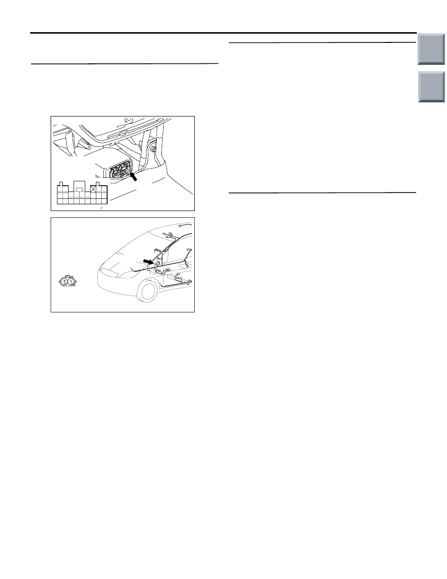
STEP 1. Check the harness wires for open circuit
or short circuit between SRS-ECU connector
B-34 (terminal No.40 and 42) and side impact
sensor (RH) connector C-27 (terminal No.1 and
2).
Q: Are the harness wires between SRS-ECU
connector B-34 (terminal No.40 and 42) and side
impact sensor (RH) connector C-27 (terminal No.1
and 2) in good condition?
YES : .
Go to Step 2.
NO : .
Repair the harness wires between
SRS-ECU connector B-34> (terminal No.40
and 42) and side impact sensor (RH)
connector C-27 (terminal No.1 and 2).
STEP 2. Check the side impact sensor (RH)
(front). (M.U.T.-III diagnosis code)
(1) Disconnect the negative battery terminal.
(2) Replace the side impact sensor (RH) (front) with
the side impact sensor (LH) (front).
(3) Connect the negative battery terminal.
(4) Erase diagnosis code from memory, and check
the diagnosis code.
Q: Is diagnosis code 94 set?
YES :
Replace the SRS-ECU (Refer to
).
NO :
Replace the side impact sensor (LH) (front)
with a new one (Refer to
Step 3 .
STEP 3. Check whether the diagnosis code is
reset.
Q: Is diagnosis code 94 set?
YES :
Replace the SRS-ECU (Refer to
).
NO :
An intermittent malfunction is suspected
(Refer to GROUP 00, How to Cope with
Intermittent Malfunction
).
AC206285
AG
B-34 (Y)
Connector: B-34
Harness side
connector
(rear view)
343536373839404142
252627282930313233
2122
2324
AC401057
AK
Connector: C-27
C-27 (Y)
Harness side
(front view)
Main
Index
Group
TOC
TROUBLESHOOTING
SUPPLEMENTAL RESTRAINT SYSTEM (SRS)
52B-131
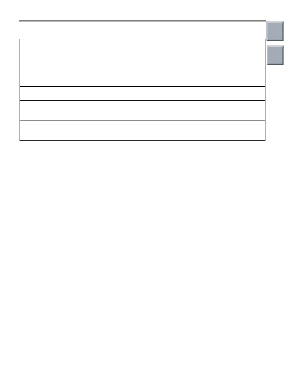
CHECK CHART FOR TROUBLE SYMPTOMS
M1524003400989
Trouble
Inspection procedure No.
Reference page
Communication with M.U.T.-III is not possible
(Communication with all systems is not
possible).
−
GROUP 13A,
Troubleshooting
GROUP 13B,
Troubleshooting
Communication with M.U.T.-III is not possible
(Communication is not possible with SRS).
1
When the ignition switch is turned to the "ON"
position (engine stopped), the SRS warning
lamp does not illuminate.
Refer to diagnosis code No.43.
After the ignition switch is turned to the "ON"
position, the SRS warning lamp does not go off
within approximately 7 seconds.
Refer to diagnosis code No.43.
Main
Index
Group
TOC
TROUBLESHOOTING
SUPPLEMENTAL RESTRAINT SYSTEM (SRS)
52B-132
SYMPTOM PROCEDURES
INSPECTION PROCEDURE 1: Communication with M.U.T.-III is not possible (Communication is not
possible with SRS).
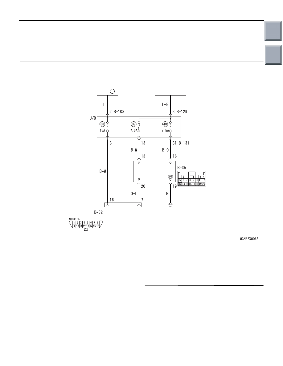
OPERATION
• The SRS-ECU is powered from the ignition
switch (IG1).
• The SRS-ECU power is supplied from two cir-
cuits. Even if one circuit is shut off, the air bag
can inflate.
• The SRS system diagnosis can be done by con-
necting M.U.T.-III to the diagnosis connector.
COMMENTS ON TROUBLE SYMPTOM
If communication is not possible with the SRS only,
the cause is probably an open circuit in the diagnosis
output circuit of the SRS or in the power circuit
(including earth circuit).
PROBABLE CAUSES
• Damaged wiring harnesses or connectors
• Malfunction of the SRS-ECU
DIAGNOSIS PROCEDURE
STEP 1. Check that the M.U.T.-III can
communicate with the other systems.
Q: Can the M.U.T.-III communicate with the other
systems?
YES :
Go to Step 2.
NO :
Refer to GROUP 13A, Troubleshooting
, GROUP 13B, Troubleshooting
.
AC510262
IGNITION
SWITCH (IG1)
SRS-ECU
FRONT SIDE
DIAGNOSIS
CONNECTOR
FUSIBLE
LINK
6
Wire colour code
B : Black LG : Light green G : Green L : Blue
W : White Y : Yellow SB : Sky blue BR : Brown
O : Orange GR : Grey R : Red P : Pink V : Violet
SRS-ECU Power Supply Circuit
AB
Main
Index
Group
TOC
TROUBLESHOOTING
SUPPLEMENTAL RESTRAINT SYSTEM (SRS)
52B-133
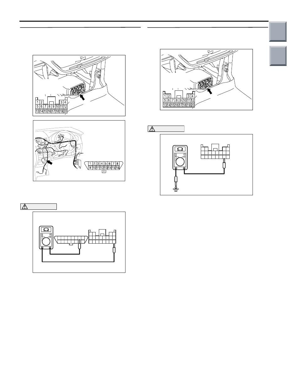
STEP 2. Resistance measurement between
SRS-ECU connector B-35 (terminal No.20) and
diagnosis connector B-32 (terminal No.7).
(1) Disconnect the negative battery terminal.
(2) Disconnect SRS-ECU connector B-35 and
diagnosis connector B-32, and measure at the
wiring harness side.
CAUTION
Do not insert a test probe into the terminal from
of the SRS-ECU connector B-35 its front side
directly as the connector contact pressure may
be weakened.
(3) Resistance measurement between the following
terminals.
• SRS-ECU connector B-35 (terminal No.20)
and diagnosis connector B-32 (terminal No.7)
OK: Continuity (Less than 2
Ω)
Q: Is the check results normal?
YES : .
Go to Step 3.
NO : .
Go to Step 5.
STEP 3. Resistance measurement the earth
circuit to the SRS-ECU connector B-35.
(1) Disconnect the negative battery terminal.
(2) Disconnect SRS-ECU connector B-35 and
measure at the wiring harness side.
CAUTION
Do not insert a test probe into the terminal from
its front side directly as the connector contact
pressure may be weakened.
(3) Check for continuity between terminal 19 and
body earth.
OK: Continuity (Less than 2
Ω)
Q: Is the check result normal?
YES :
Go to Step 4.
NO :
Check the harness wire for open circuit
between SRS-ECU connector B-35
(terminal No.19) and earth, and repair if
necessary.
AC206285
AF
B-35 (Y)
Connector: B-35
Harness side
connector
(rear view)
AC313822 AC
Connector: B-32
Harness side
(Front side)
1314151617181920
5 6 7 8 9 101112
1 2
3 4
1 2 3 4 5 6 7 8
9 10111213141516
AC006263
B-35 Harness side
connector (rear view)
Diagnosis
connector
AO
B-32
AC206285
AF
B-35 (Y)
Connector: B-35
Harness side
connector
(rear view)
AC209044
1314151617181920
5 6 7 8 9 101112
1 2
3 4
B-35 Harness side connector
(rear view)
AE
Main
Index
Group
TOC
Нет комментариевНе стесняйтесь поделиться с нами вашим ценным мнением.
Текст