Mitsubishi Colt Ralliart. Manual — part 579

SIDE AND CURTAIN AIR BAG MODULES
SUPPLEMENTAL RESTRAINT SYSTEM (SRS)
52B-154
INSTALLATION SERVICE POINTS
>>A<< PRE-INSTALLATION INSPECTION
WARNING
Dispose of air bag modules only according
to the specified procedure (Refer to
1. When installing the new air bag modules, refer to
“INSPECTION” (
2. Connect the negative (
−) battery cable.
CAUTION
To prevent damage to M.U.T.-III, always turn the
ignition, switch to the “LOCK” (OFF) position
before connecting or disconnecting M.U.T.-III.
3. Connect M.U.T.-III to the diagnosis connector.
4. Turn the ignition switch to the “ON” position.
5. Check diagnosis codes using M.U.T.-III to ensure
that the SRS operates properly.
Confirm that the diagnosis codes other than 71,
81, 3A and 4A are not set.
DANGER
Wait at least 60 seconds after disconnecting
the battery cable before doing any further
work. (Refer to
6. Turn the ignition switch to the "LOCK" (OFF)
position.
7. Disconnect the negative (
−) battery cable and
tape the terminal to prevent accidental connection
and air bags deployment.
>>B<< CURTAIN AIR BAG HARNESS
INSTALLATION
CAUTION
• Secure the harness clip certainly and return it
to the back side of air bag.
• Connect the connector with the inflator cer-
tainly.
>>C<< CURTAIN AIR BAG MODULE
INSTALLATION
CAUTION
•
Take care not to contort the curtain air bag when
installing it.
• Take care that the surrounding components
do not trap the air bag.
• Take care that the front pillar trim clips or
other do not trap the strap.
Hang the strap on the strap guide.
>>D<< POST-INSTALLATION
INSPECTION
1. Reconnect the negative (
−) battery cable.
2. Turn the ignition switch to “ON” position.
AC206895
AC
Diagnosis
connector
MB991827
MB991824
MB991910
AC208759AC
Strap guide
Strap
Main
Index
Group
TOC
SIDE AND CURTAIN AIR BAG MODULES
SUPPLEMENTAL RESTRAINT SYSTEM (SRS)
52B-155
3. Does the "SRS" warning light illuminate for
approximately seven seconds, and go out?
4. If yes, the SRS system is functioning properly. If
.
INSPECTION
M1524014900074
FRONT SEATBACK ASSEMBLY WITH
SIDE-AIRBAG MODULE CHECK
WARNING
•
If any improper part is found during the fol-
lowing inspection, replace the front seat-
back assembly with a new one. Dispose
of the old one according to the specified
procedure (Refer to
).
•
Never attempt to measure the circuit
resistance of the air bag module (squib)
even if you are using the specified tester.
If the circuit resistance is measured with a
tester, accidental air bag deployment will
result in serious personal injury.
1. Check the air bag module deployment section for
dents or deformation.
2. Check connector for damage, terminals for
deformation, and harness for binds.
AC510172
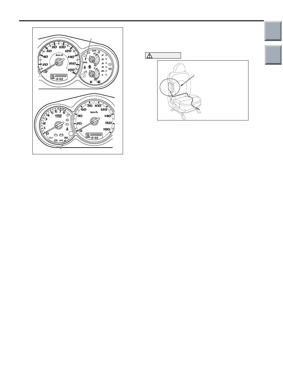
<VR-X>
<Except-VR-X>
SRS warning lamp
SRS warning lamp
AC
AC208794AF
Side-airbag module
deployment section
Main
Index
Group
TOC
SIDE AND CURTAIN AIR BAG MODULES
SUPPLEMENTAL RESTRAINT SYSTEM (SRS)
52B-156
CURTAIN AIR BAG MODULE CHECK
WARNING
•
If any improper part is found during the fol-
lowing inspection, replace the curtain air
bag module (squib) assembly with a new
one. Dispose of the old one according to
the specified procedure (Refer to
).
•
Never attempt to measure the circuit
resistance of the air bag module (squib)
even if you are using the specified tester.
If the circuit resistance is measured with a
tester, accidental air bag deployment will
result in serious personal injury.
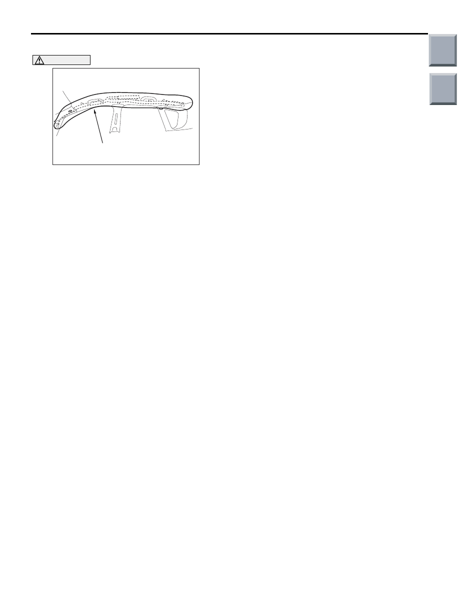
1. Check that the curtain air bag deployment part of
the headlining is normal.
2. Check the inflator surface for cracks, dents or
deformations.
3. Check the air bag for breakage.
4. Check the connector for damage, the terminal for
deformation and the harness for binding.
AC208936
Curtain air bag module
deployment section
AC
Main
Index
Group
TOC
SIDE IMPACT SENSOR
SUPPLEMENTAL RESTRAINT SYSTEM (SRS)
52B-157
SIDE IMPACT SENSOR
REMOVAL AND INSTALLATION
M1524004600771
WARNING
•
Disconnect the negative battery terminal and wait for 60 seconds or more before starting
work. Furthermore, the disconnected battery terminal should be covered with tape to
insulate it.
•
Never attempt to disassemble or repair the side impact sensors. If faulty, replace it.
•
Do not drop or subject the side impact sensors to impact or vibration. If denting, cracking,
deformation, or rust are discovered in the side impact sensors, replace it with a new front
impact sensor. Discard the old one.
•
After deployment of an air bag, replace the side impact sensors with a new one.
•
Never use an ohmmeter on or near the side impact sensors, and use only the special test
equipment described on
.
NOTE: The figure shows the side impact sensor
(LH).
Pre-removal Operation
• Turn the ignition key to the "LOCK" (OFF) position.
• Disconnect the Negative Battery Terminal.
AC207920
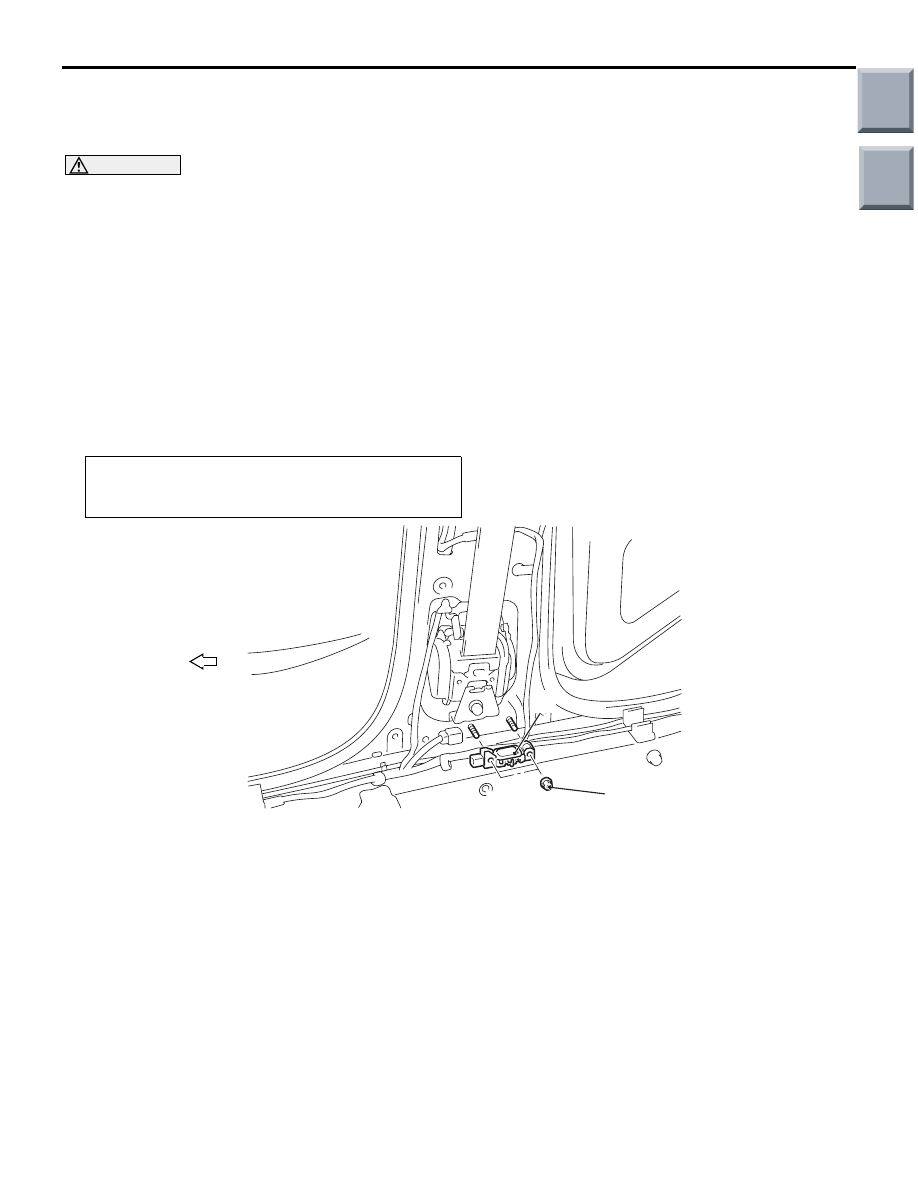
10 ± 2 N·m
AD
1
Forward
Side impact sensor removal
steps
•
Centre pillar trim lower (Refer to
GROUP 52A, Trims
1.
Side impact sensor
Side impact sensor installation
steps
>>
A
<<
•
Pre-installation inspection
>>
B
<<
1.
Side impact sensor
•
Centre pillar trim lower (Refer to
GROUP 52A, Trims
•
Negative battery cable connector
>>
C
•
Post-installation inspection
Side impact sensor installation
steps (Continued)
Main
Index
Group
TOC
Нет комментариевНе стесняйтесь поделиться с нами вашим ценным мнением.
Текст