Mitsubishi Colt Ralliart. Manual — part 578

DRIVER'S AND PASSENGER'S (FRONT) AIR BAG MODULES AND CLOCK SPRING
SUPPLEMENTAL RESTRAINT SYSTEM (SRS)
52B-150
>>C<< STEERING WHEEL/DRIVER’S AIR
BAG MODULE INSTALLATION
CAUTION
When installing the steering wheel, and driver’s
air bag module ensure that the harness of the
clock spring does not become caught or tangled.
1. Before installing the steering wheel, and driver’s
air bag module turn the vehicle’s front wheels to
the straight-ahead position and align the mating
marks of the clock spring.
2. After securing the steering wheel, turn the
steering wheel all the way in both directions to
confirm that the steering wheel rotation is normal.
>>D << COVER INSTALLATION
1. Secure the horn connector to the cover.
2. Install the cover to the steering wheel assembly.
>>E<< POST-INSTALLATION
INSPECTION
1. Reconnect the negative (
−) battery cable.
2. Turn the ignition switch to “ON” position.
3. Does the "SRS" warning lamp illuminate for
approximately seven seconds, and go out?
4. If yes, the SRS system is functioning properly. If
no, refer to
.
AC209070AE
Horn connector fixing point
Cover
AC510172
<VR-X>
<Except-VR-X>
SRS warning lamp
SRS warning lamp
AC
Main
Index
Group
TOC
DRIVER'S AND PASSENGER'S (FRONT) AIR BAG MODULES AND CLOCK SPRING
SUPPLEMENTAL RESTRAINT SYSTEM (SRS)
52B-151
INSPECTION
M1524014600244
AIR BAG MODULE CHECK
WARNING
•
If any component damage is found during
the following inspection, replace the air
bag module(s) with a new one. Dispose of
the old one according to the specified
procedure (Refer to
).
•
Never attempt to measure the circuit
resistance of he air bag module (squib)
even if you are using the specified tester.
If the circuit resistance is measured with a
tester, accidental air bag module(s)
deployment will result in serious personal
injury.
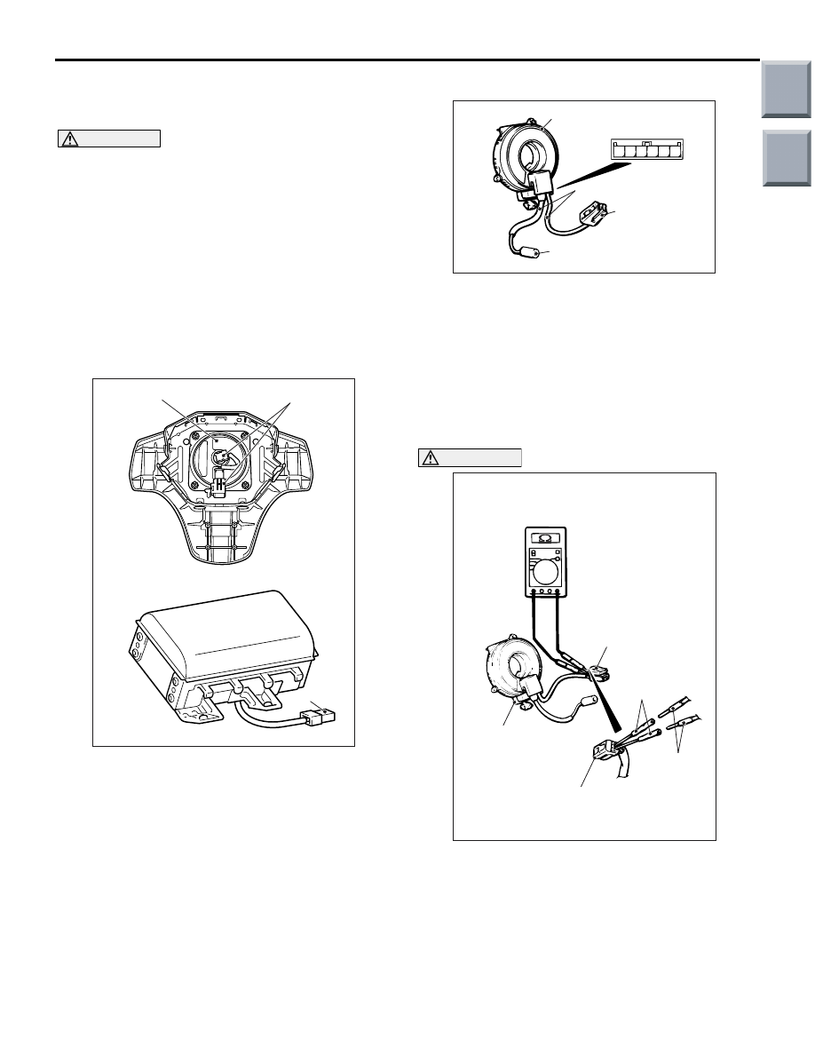
1. Check the pad cover for dents, cracks or
deformation.
2. Check the connectors for damage, the terminals
for deformation, and the harness for binds.
3. Check the air bag inflator case for dents, cracks or
deformation.
4. Install the driver’s air bag module to the steering
wheel and check fit and alignment with the wheel.
5. Install the passenger’s (front) air bag module to
the instrument panel and front deck crossmember
and check fit and alignment.
CLOCK SPRING CHECK
If any malfunction is found in the following inspec-
tions, replace the clock spring with a new one.
1. Check the connectors and protective tube for
damage, and the terminals for deformation.
2. Visually check the case for damage.
3. Check to see that there is a charge (continuity)
between the B-137 clock spring connector
terminal 1 and B-139 horn switch.
CAUTION
Do not directly insert a probe, etc. into the termi-
nal from the front of the connector.
4. Insert the special tool extra fine probe
(MB992006) from behind the B-138 driver’s air
bag module connector.
5. As shown in the Figure, connect the circuit tester
to the special tool extra fine probe (MB992006)
and check to see that there is a charge between
the terminals.
AC208717
Connector
Inflator case
Connector
AC
5 6
1 2 3 4
AC300312AE
Case
B-137 Clock spring
connector
Protective tube
B-138 Air bag
module connector
B-139 Horn switch
AC100448
Clock spring
MB992006
Digital
multi-meter
AS
B-138 Driver's air bag
module connector
B-138 Driver's air bag
module connector
Main
Index
Group
TOC
SIDE AND CURTAIN AIR BAG MODULES
SUPPLEMENTAL RESTRAINT SYSTEM (SRS)
52B-152
SIDE AND CURTAIN AIR BAG MODULES
REMOVAL AND INSTALLATION
M1524014800248
WARNING
•
Disconnect the negative battery terminal and wait for 60 seconds or more before starting
work. Also, the disconnected battery terminal should be insulated with tape (Refer to
).
•
Never attempt to disassemble or repair the air bag modules. If faulty, just replace with new
one(s).
•
Do not drop the air bag modules or allow contact with water, grease or oil. Replace if a
dent, crack, deformation or rust are present.
•
Store the air bag modules on a flat surface with the deployment surface facing up. Do not
place anything on top of them.
•
Do not store the air bag modules in a place more than 93
°
C.
•
When the side and curtain air bags have been deployed, replace the front seatback
assembly and curtain air bag modules with new ones.
•
Put on gloves and safety glasses when handling deployed air bags.
•
When discarding the undeployed air bag module(s), be sure to deploy the air bag(s) in
advance as specified in the service procedure (Refer to
).
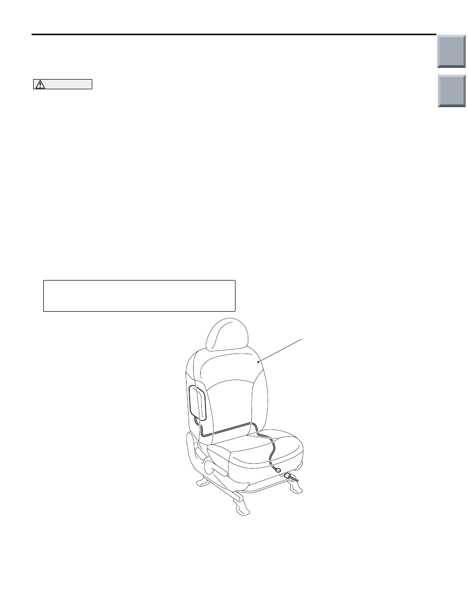
<SIDE-AIRBAG MODULE>
Pre-removal Operation
• Turn the ignition switch to the "LOCK" (OFF) position.
• Disconnect the Negative Battery Terminal.
AC208417
1
AD
Side air bag module removal steps
<<
A
>>
1. Front seat assembly
Side air bag module installation
steps
>>
A
<< • Pre-installation inspection
1. Front seat assembly
•
Negative (
−) battery cable connection
>>
D
<< • Post-installation inspection
Side air bag module installation
steps (Continued)
Main
Index
Group
TOC
SIDE AND CURTAIN AIR BAG MODULES
SUPPLEMENTAL RESTRAINT SYSTEM (SRS)
52B-153
<CURTAIN AIR BAG MODULE>
REMOVAL SERVICE POINTS
<<A>> FRONT SEAT ASSEMBLY
REMOVAL
WARNING
Dispose of air bag modules only according
to the specified procedure (Refer to
Refer to GROUP52A, Front seat assembly
.
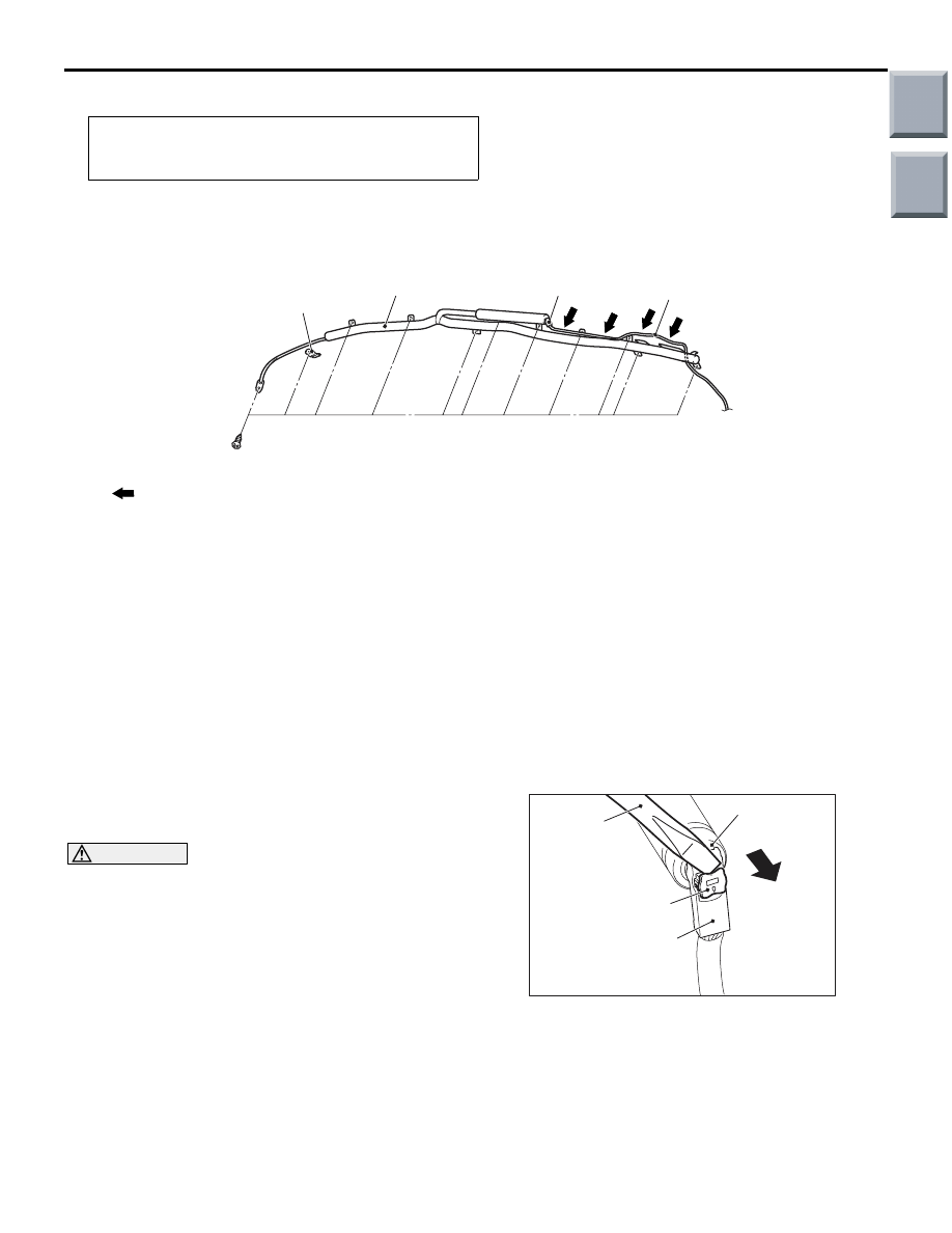
<<B>> CONNECTOR REMOVAL
Use a flat-tipped screwdriver to pull out forward and
unlock the locking button of the curtain air bag har-
ness-side connector.
Pre-removal Operation
• Turn the ignition switch to the "LOCK" (OFF) position.
• Disconnect the Negative Battery Terminal.
AC208406
NOTE
: Harness clip positions
AC
1
3
2
4
Curtain air bag module removal
steps
•
Headlining (Refer to GROUP 52A,
Headlining
.)
<<
B
>>
1. Connector
2. Curtain air bag module
3. Strap guide bracket
4. Curtain air bag harness
Curtain air bag module installation
steps
>>
A
<< • Pre-installation inspection
>>
B
<< 4. Curtain air bag harness
3. Strap guide bracket
>>
C
<< 2. Curtain air bag module
1. Connector
•
Headlining (Refer to GROUP 52A,
Headlining
.)
•
Negative (
−) battery cable connection
>>
D
<< • Post-installation inspection
AC208384 AC
Locking button
Inflator connector
Curtain air bag
harness connector
Flat-tip screw
driver
Main
Index
Group
TOC
Нет комментариевНе стесняйтесь поделиться с нами вашим ценным мнением.
Текст