Mitsubishi Colt Ralliart. Manual — part 235
TROUBLESHOOTING
ANTI-SKID BRAKING SYSTEM (ABS)
35B-32
DIAGNOSTIC PROCEDURE
STEP 1. Connector check: C-17 rear left wheel
speed sensor connector
Q: Is the check result normal?
YES :
Go to Step 2.
NO :
Repair the defective connector.
STEP 2. Remove the rear left wheel speed sensor
and check it.
Refer to
Q: Is the check result normal?
YES :
Go to Step 3.
NO :
Replace the rear left wheel speed sensor
(Refer to
STEP 3. Check the wheel bearing for excessive
play.
Refer to GROUP 27, On-vehicle Service
− Wheel
Bearing Axial Play Check
Q: Is the check result normal?
YES :
Go to Step 4.
NO :
Replace the hub assembly (Refer to
GROUP 27, Rear Axle Hub
).
STEP 4. Check the encoder for detecting wheel
speed.
Check the encoder for presence of foreign objects or
deformation.
Q: Is the check result normal?
YES :
Go to Step 5.
NO :
If foreign objects are found, clean the
encoder. If deformation is found, replace the
hub (Refer to GROUP 27, Rear Axle Hub
).
STEP 5. Check whether the diagnosis code is
reset.
CAUTION
Before connecting or disconnecting the
M.U.T.-III, turn the ignition switch to the "LOCK"
(OFF) position.
Check again if the diagnosis code is set.
(1) Turn the ignition switch to the "ON" position.
(2) Erase the diagnosis code.
(3) Turn the ignition switch to the "LOCK" (OFF)
position.
(4) Turn the ignition switch to the "ON" position.
(5) Check if the diagnosis code is set.
(6) Turn the ignition switch to the "LOCK" (OFF)
position.
(7) Disconnect M.U.T.-III.
Q: Is code No.C1216 set?
YES :
Replace the hydraulic unit (integrated with
ABS-ECU) (Refer to
).
NO :
The malfunction is intermittent. Refer to
GROUP 00, How to Use
Troubleshooting/Inspection Service Points
−
How to Cope with Intermittent Malfunction
.
AC313878
Connector: C-17
AC
Harness side
C-17(B)
AC206895
AC
Diagnosis
connector
MB991827
MB991824
MB991910
Main
Index
Group
TOC

TROUBLESHOOTING
ANTI-SKID BRAKING SYSTEM (ABS)
35B-33
Code No.C1266: Motor system (stuck)
OPERATION
• The ABS-ECU contains the power supply circuit
(terminal No.25) for the motor pump. The motor
pump is energised by the pump relay, which is
incorporated in the ABS-ECU.
• The pump relay, which is incorporated in the
ABS-ECU, is always energising the motor pump
unless the initial check is in progress when the
ignition switch is turned on, or the recurrent sys-
tem check is in progress.
DIAGNOSIS CODE SET CONDITIONS
These diagnosis codes will be set under the cases
below.
• The ABS-ECU monitors the voltage, which is cre-
ated by the pump motor coasting, after the motor
relay is turned off. If the voltage continues only for
too short period, the ECU determines that the
pump motor is not running smoothly (i.e. motor
seizure), and sets this diagnosis code.
PROBABLE CAUSES
The most likely causes for these diagnosis codes to
set are:
• Damaged wiring harness or connector
• Malfunction of the hydraulic unit (integrated with
ABS-ECU)
IGNITION
SWITCH (IG1)
ELECTRIC
POWER
STEERING
SYSTEM
ABS-ECU
Wire colour code
B : Black LG : Light green G : Green L : Blue W : White Y : Yellow SB : Sky blue
BR : Brown O : Orange GR : Gray R : Red P : Pink V : Violet
Power Supply Circuit
Main
Index
Group
TOC

TROUBLESHOOTING
ANTI-SKID BRAKING SYSTEM (ABS)
35B-34
DIAGNOSIS PROCEDURE
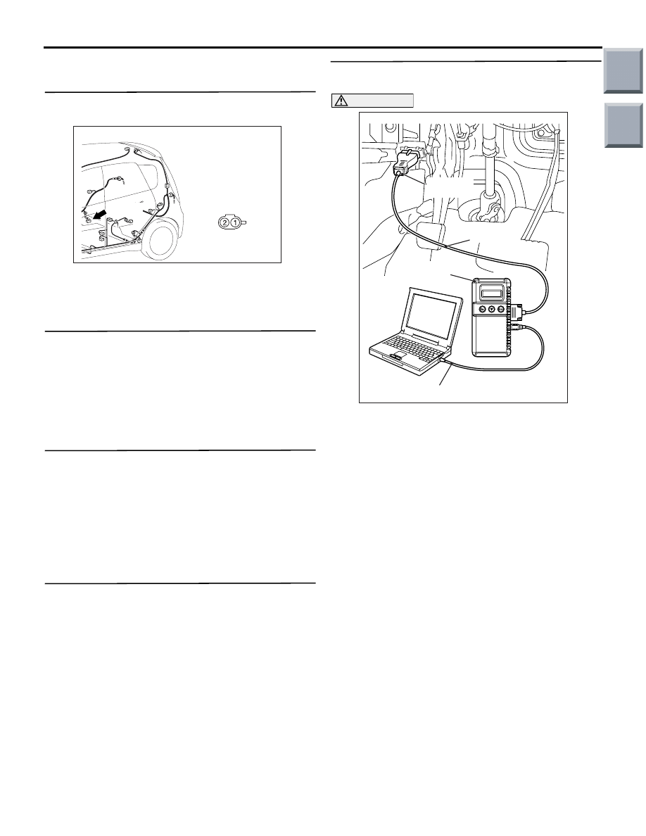
STEP 1. M.U.T.-III diagnosis code
CAUTION
Before connecting or disconnecting the
M.U.T.-III, turn the ignition switch to the "LOCK"
(OFF) position.
(1) Turn the ignition switch to the "ON" position.
(2) Check if the diagnosis code is set.
(3) Turn the ignition switch to the "LOCK" (OFF)
position.
Q: Is code No.C1273 set?
YES : .
Carry out the troubleshooting for diagnosis
code C1273 (Refer to
).
NO : .
Go to Step 2.
STEP 2. Check ABS-ECU connector A-05 for
loose, corroded or damaged terminals, or
terminals pushed back in the connector.
Q: Is the check result normal?
YES :
Go to Step 3.
NO :
Repair or replace the damaged
component(s). Refer to GROUP 00, How to
Use Troubleshooting/Inspection Service
Points
− Connector Inspection Service
Points
AC206895
AC
Diagnosis
connector
MB991827
MB991824
MB991910
AC313863AB
Connector: A-05
Harness side
A-05(B)
Main
Index
Group
TOC

TROUBLESHOOTING
ANTI-SKID BRAKING SYSTEM (ABS)
35B-35
STEP 3. Check the harness wire between the
ABS-ECU connector A-05 terminal 20 and
ignition switch (IG1).
NOTE:
After inspecting connector B-129 and B-110, inspect
the wire. If connector B-129 or B-110 is damaged,
repair or replace it.
Q: Is the harness wire between the ABS-ECU
connector A-05 terminal 20 and ignition switch
(IG1) damaged?
YES :
Repair the harness wire and then go to Step
6.
NO :
Go to Step 4.
AC313863AB
Connector: A-05
Harness side
A-05(B)
AC313870AI
Connector: B-110
Junction Block (Front view)
Junction block side
12
5
9
8
1 2
1011
3 4
14
13
6 7
AC313872AJ
Connector: B-129
Junction Block (Rear view)
Junction block side
Main
Index
Group
TOC
Нет комментариевНе стесняйтесь поделиться с нами вашим ценным мнением.
Текст