Mitsubishi Colt Ralliart. Manual — part 233
TROUBLESHOOTING
ANTI-SKID BRAKING SYSTEM (ABS)
35B-24
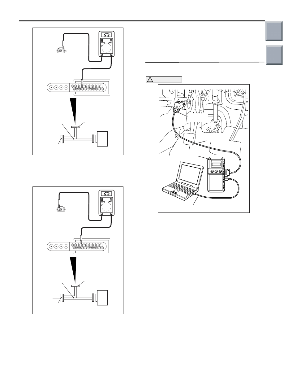
(2) Resistance between ABS-ECU connector A-05
terminal 19 and rear right wheel speed sensor
C-06 terminal 1
OK: 10
Ω or less
(3) Resistance between ABS-ECU connector A-05
terminal 8 and rear right wheel speed sensor
C-06 terminal 2
OK: 10
Ω or less
Q: Is the check result normal?
YES :
Go to Step 6.
NO :
Repair the wiring harness between
ABS-ECU connector A-05 and rear right
wheel speed sensor connector C-06.
STEP 6. Check whether the diagnosis code is
reset.
CAUTION
Before connecting or disconnecting the
M.U.T.-III, turn the ignition switch to the "LOCK"
(OFF) position.
Check again if the diagnosis code is set.
(1) Turn the ignition switch to the "ON" position.
(2) Erase the diagnosis code.
(3) Turn the ignition switch to the "LOCK" (OFF)
position.
(4) Turn the ignition switch to the "ON" position.
(5) Check if the diagnosis code is set.
(6) Turn the ignition switch to the "LOCK" (OFF)
position.
(7) Disconnect M.U.T.-III.
Q: Is code No.C1210 set?
YES :
Replace the hydraulic unit (integrated with
ABS-ECU) (Refer to
).
NO :
The malfunction is intermittent. Refer to
GROUP 00, How to Use
Troubleshooting/Inspection Service Points
−
How to Cope with Intermittent Malfunction
.
AC314119AH
C-06 Harness
connector:
Harness side
MB991951
Check
connector
ABS-ECU
A-05 Harness connector
AC314119AI
C-06 Harness
connector:
Harness side
MB991951
Check
connector
ABS-ECU
A-05 Harness connector
AC206895
AC
Diagnosis
connector
MB991827
MB991824
MB991910
Main
Index
Group
TOC

TROUBLESHOOTING
ANTI-SKID BRAKING SYSTEM (ABS)
35B-25
Code No.C1211: Wheel speed sensor (RR) system (sensor output failure)
OPERATION
The wheel speed sensor is a pulse generator. It con-
sists of encoder (a plate on which north and south
pole sides of the magnets are arranged alternately)
for detecting wheel speed which rotates at the same
speed as the road wheels. This sensor sends fre-
quency pulse signals in proportion to wheel speed.
The pulse signals, which the wheel speed sensor
creates, are sent to the ABS-ECU. The ABS-ECU
uses the frequency of the pulse signals to determine
the wheel speed.
DIAGNOSIS CODE SET CONDITIONS
The ABS-ECU monitors the signals from the wheel
speed sensors during driving. If the ECU detects
malfunctions below, it sets the diagnosis code.
• Missing of wheel speed sensor signals
• When an abnormal wheel speed sensor signal is
received
• When one of the wheel speed sensor signals
(from the front, rear, right and left wheels) is sig-
nificantly different from the others
PROBABLE CAUSES
• Improperly installed wheel speed sensor
• Presence of dirt or other foreign particles on the
encoder of the wheel speed sensor
• Deformed encoder of the wheel speed sensor
• Excessive gap between the wheel speed sensor
and its encoder
• Damaged wiring harness or connector
• Malfunction of the wheel speed sensor
• Malfunction of the hydraulic unit (integrated with
ABS-ECU)
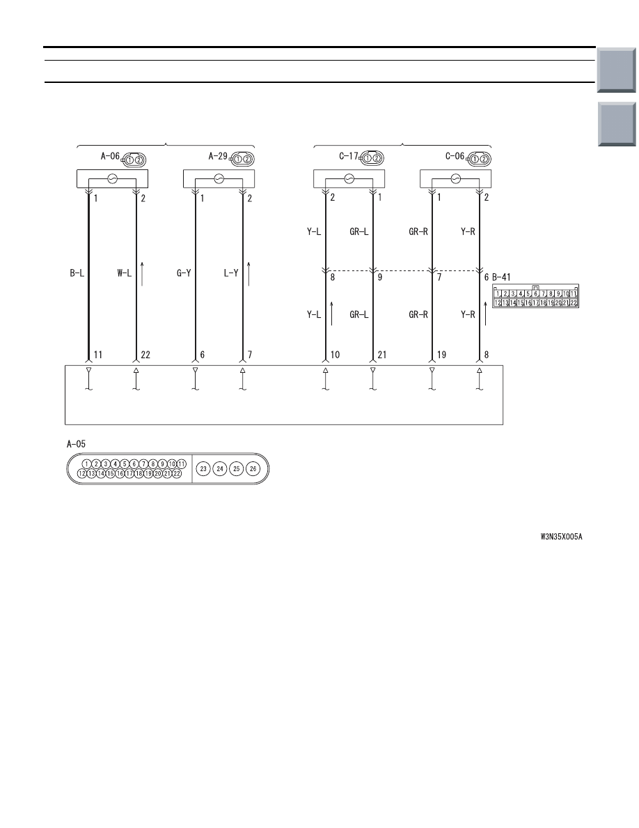
FRONT WHEEL SPEED SENSOR
(LH)
(RH)
(LH)
(RH)
ABS-ECU
REAR WHEEL SPEED SENSOR
Wire colour code
B : Black LG : Light green G : Green L : Blue W : White Y : Yellow SB : Sky blue
BR : Brown O : Orange GR : Gray R : Red P : Pink V : Violet
Wheel Speed Sensor Circuit
Main
Index
Group
TOC

TROUBLESHOOTING
ANTI-SKID BRAKING SYSTEM (ABS)
35B-26
DIAGNOSIS PROCEDURE
STEP 1. Connector check: C-06 rear right wheel
speed Sensor connector
Q: Is the check result normal?
YES :
Go to Step 2.
NO :
Repair the defective connector.
STEP 2. Remove the rear right wheel speed
sensor and check it.
Refer to
Q: Is the check result normal?
YES :
Go to Step 3.
NO :
Replace the rear right wheel speed sensor
(Refer to
STEP 3. Check the wheel bearing for excessive
play.
Refer to GROUP 27, On-vehicle Service
− Wheel
Bearing Axial Play Check
Q: Is the check result normal?
YES :
Go to Step 4.
NO :
Replace the hub assembly (Refer to
GROUP 27, Rear Axle Hub
).
STEP 4. Check the encoder for detecting wheel
speed.
Check the encoder for presence of foreign objects or
deformation.
Q: Is the check result normal?
YES :
Go to Step 5.
NO :
If foreign objects are found, clean the
encoder. If deformation is found, replace the
hub (Refer to GROUP 27, Rear Axle Hub
).
STEP 5. Check whether the diagnosis code is
reset.
CAUTION
Before connecting or disconnecting the
M.U.T.-III, turn the ignition switch to the "LOCK"
(OFF) position.
Check again if the diagnosis code is set.
(1) Turn the ignition switch to the "ON" position.
(2) Erase the diagnosis code.
(3) Turn the ignition switch to the "LOCK" (OFF)
position.
(4) Turn the ignition switch to the "ON" position.
(5) Check if the diagnosis code is set.
(6) Turn the ignition switch to the "LOCK" (OFF)
position.
(7) Disconnect M.U.T.-III.
Q: Is code No.C1211 set?
YES :
Replace the hydraulic unit (integrated with
ABS-ECU) (Refer to
).
NO :
The malfunction is intermittent. Refer to
GROUP 00, How to Use
Troubleshooting/Inspection Service Points
−
How to Cope with Intermittent Malfunction
.
AC313878
Connector: C-06
AB
Harness side
C-06(B)
AC206895
AC
Diagnosis
connector
MB991827
MB991824
MB991910
Main
Index
Group
TOC
TROUBLESHOOTING
ANTI-SKID BRAKING SYSTEM (ABS)
35B-27
Code No.C1215: Wheel speed sensor (RL) system (open circuit, short to earth or power supply)
OPERATION
The wheel speed sensor is a pulse generator. It con-
sists of encoder (a plate on which north and south
pole sides of the magnets are arranged alternately)
for detecting wheel speed which rotates at the same
speed as the road wheels. This sensor sends fre-
quency pulse signals in proportion to wheel speed.
The pulse signals, which the wheel speed sensor
creates, are sent to the ABS-ECU. The ABS-ECU
uses the frequency of the pulse signals to determine
the wheel speed.
DIAGNOSIS CODE SET CONDITIONS
The ABS-ECU monitors the voltage change in each
of the wheel speed sensor circuits. If the ECU
detects an open or short circuit in any of the circuits,
the ECU sets the diagnosis code.
PROBABLE CAUSES
• Damaged wiring harness or connector
• Malfunction of the wheel speed sensor
• Malfunction of the hydraulic unit (integrated with
ABS-ECU)
FRONT WHEEL SPEED SENSOR
(LH)
(RH)
(LH)
(RH)
ABS-ECU
REAR WHEEL SPEED SENSOR
Wire colour code
B : Black LG : Light green G : Green L : Blue W : White Y : Yellow SB : Sky blue
BR : Brown O : Orange GR : Gray R : Red P : Pink V : Violet
Wheel Speed Sensor Circuit
Main
Index
Group
TOC
Нет комментариевНе стесняйтесь поделиться с нами вашим ценным мнением.
Текст