Mitsubishi Colt Ralliart. Manual — part 236
TROUBLESHOOTING
ANTI-SKID BRAKING SYSTEM (ABS)
35B-36
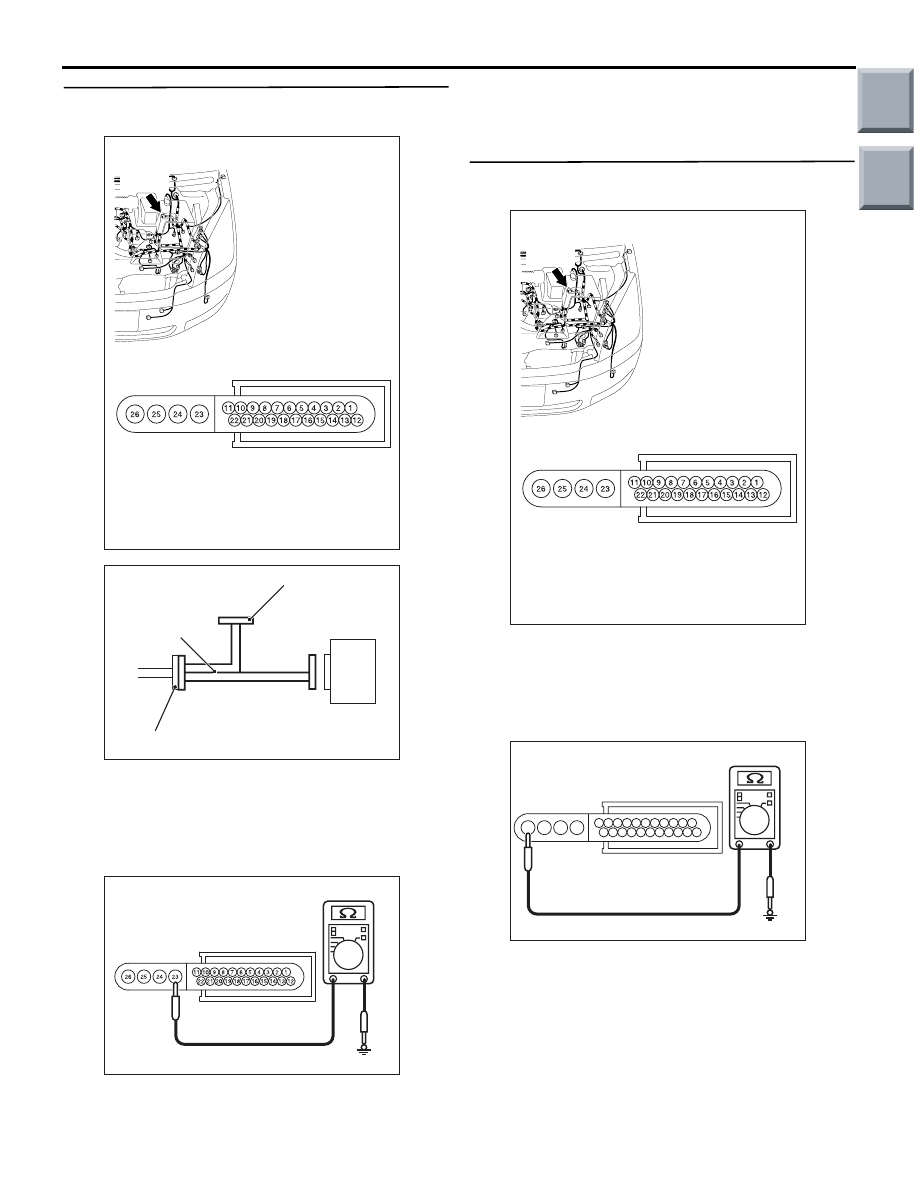
STEP 4. Resistance measurement at ABS-ECU
connector A-05.
(1) Disconnect the connector A-05, and connect
special tool ABS Check Harness (MB991951) to
the wiring harness-side connector.
NOTE: Do not connect special tool ABS Check
Harness (MB991951) to the ABS-ECU.
(2) Measure the resistance between terminal 23 and
earth.
OK: 5
Ω or less
Q: Is the result normal?
YES :
Go to Step 6.
NO :
Go to Step 5.
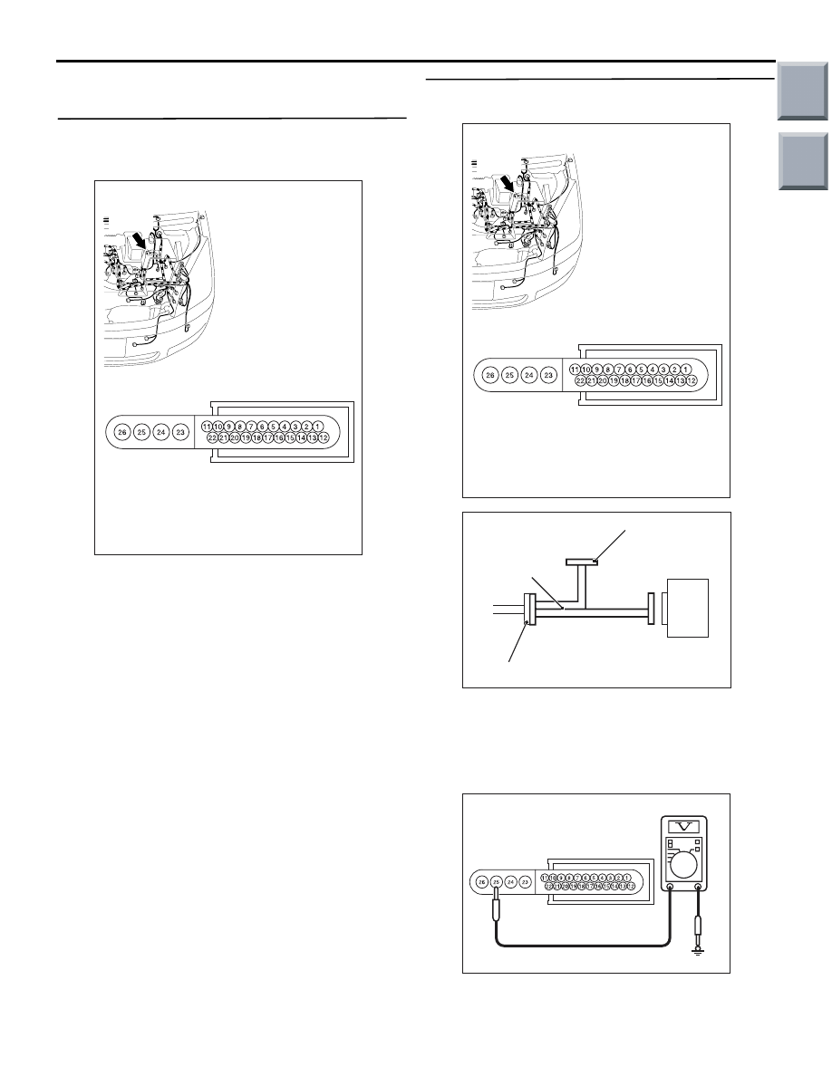
STEP 5. Resistance measurement at ABS-ECU
connector A-05.
(1) Disconnect the connector A-05, and connect
special tool ABS Check Harness (MB991951) to
the wiring harness-side connector.
NOTE: Do not connect special tool ABS Check
Harness (MB991951) to the ABS-ECU.
(2) Measure the resistance between terminal 26 and
earth.
OK: 5
Ω or less
Q: Is the result normal?
YES :
Go to Step 6.
NO :
Repair the wiring harness between the
ABS-ECU and body earth.
AC313863AB
Connector: A-05
Harness side
A-05(B)
AC314249AB
ABS-ECU
MB991951
Check connector
A-05 Harness connector
AC313972BH
Check connector
(Harness side)
AC313863AB
Connector: A-05
Harness side
A-05(B)
AC313972BB
1
2
3
4
5
7
8
9
10
11
18
19
20
21
22
13
14
15
16
17
6
12
23
24
25
26
Check connector
(Harness side)
Main
Index
Group
TOC

TROUBLESHOOTING
ANTI-SKID BRAKING SYSTEM (ABS)
35B-37
STEP 6. Check whether the diagnosis code is
reset.
CAUTION
Before connecting or disconnecting the
M.U.T.-III, turn the ignition switch to the "LOCK"
(OFF) position.
(1) Turn the ignition switch to the "ON" position.
(2) Erase the diagnosis code.
(3) Turn the ignition switch to the "LOCK" (OFF)
position.
(4) Turn the ignition switch to the "ON" position.
(5) Check if the diagnosis code is set.
(6) Turn the ignition switch to the "LOCK" (OFF)
position.
(7) Disconnect M.U.T.-III.
Q: Is code No.C1266 set?
YES :
Replace the hydraulic unit (integrated with
ABS-ECU) (Refer to
).
NO :
The malfunction is intermittent. Refer to
GROUP 00, How to Use
Troubleshooting/Inspection Service Points
−
How to Cope with Intermittent Malfunction
.
AC206895
AC
Diagnosis
connector
MB991827
MB991824
MB991910
Main
Index
Group
TOC

TROUBLESHOOTING
ANTI-SKID BRAKING SYSTEM (ABS)
35B-38
Code No.C1273: Motor relay stuck off
OPERATION
• The ABS-ECU contains the power supply circuit
(terminal No.25) for the motor pump. The motor
pump is energised by the pump relay, which is
incorporated in the ABS-ECU.
• The pump relay, which is incorporated in the
ABS-ECU, is always energising the motor pump
unless the initial check is in progress when the
ignition switch is turned on, or the recurrent sys-
tem check is in progress.
DIAGNOSIS CODE SET CONDITIONS
These diagnosis codes will be set under the cases
below.
• If the voltage, which is created by the pump
motor, is abnormal after the motor relay is turned
on, the ECU determines that the motor relay is
stuck off, and sets this diagnosis code.
PROBABLE CAUSES
The most likely causes for these diagnosis codes to
set are:
• Damaged wiring harness or connector
• Malfunction of the hydraulic unit (integrated with
ABS-ECU)
ABS-ECU
SOLENOID
VALVE POWER
SOURCE
MOTOR POWER SOURCE
MOTOR
SOLENOID VALVE
HYDRAULIC UNIT
FUSIBLE
LINK
FUSIBLE
LINK
CHARGING
SYSTEM
3
5
Wire colour code
B : Black LG : Light green G : Green L : Blue W : White Y : Yellow SB : Sky blue
BR : Brown O : Orange GR : Gray R : Red P : Pink V : Violet
Hydraulic Unit (Motor and Solenoid Valve) Circuit
Main
Index
Group
TOC
TROUBLESHOOTING
ANTI-SKID BRAKING SYSTEM (ABS)
35B-39
DIAGNOSIS PROCEDURE
STEP 1. Check ABS-ECU connector A-05 for
loose, corroded or damaged terminals, or
terminals pushed back in the connector.
Q: Is the check result normal?
YES :
Go to Step 2.
NO :
Repair or replace the damaged
component(s). Refer to GROUP 00, How to
Use Troubleshooting/Inspection Service
Points
− Connector Inspection Service
Points
.
STEP 2. Voltage measurement at ABS-ECU
connector A-05.
(1) Disconnect the connector A-05, and connect
special tool ABS Check Harness (MB991951) to
the wiring harness-side connector.
NOTE: Do not connect special tool ABS Check
Harness (MB991951) to the ABS-ECU.
(2) Measure the voltage between terminal 25 and
earth.
OK: System voltage
AC313863AB
Connector: A-05
Harness side
A-05(B)
AC313863AB
Connector: A-05
Harness side
A-05(B)
AC314249AB
ABS-ECU
MB991951
Check connector
A-05 Harness connector
AC313972 BS
Check connector
(Harness side)
Main
Index
Group
TOC
Нет комментариевНе стесняйтесь поделиться с нами вашим ценным мнением.
Текст