Mitsubishi Colt Ralliart. Manual — part 608
ROCKER ARMS AND CAMSHAFT
ENGINE OVERHAUL <4G1>
11D-32
NOTE: If the lash adjuster contracts, perform the
operations 7 through 9 again. Replace the lash
adjuster if it still contracts even after the pressure
chamber has completely been filled with diesel
fuel (air has been bled).
10.Keep the serviced lash adjusters in their upright
positions to prevent diesel fuel from spilling out.
Protect them from dust or other foreign matter.
Install the lash adjusters onto the engine as soon
as possible.
Main
Index
Group
TOC
CYLINDER HEAD AND VALVES
ENGINE OVERHAUL <4G1>
11D-33
CYLINDER HEAD AND VALVES
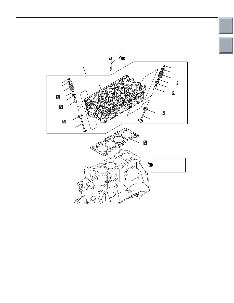
REMOVAL AND INSTALLATION
M1113006901003
AK202373
49 ± 2 N·m
→ 0 N·m → 20 ± 2 N·m → 90˚ + 90˚
1
2
15
16
14
9
11
19
12
13
10
20
18
7
17
8
4
5
6
3
AD
Apply engine oil to
all moving parts
before installation.
Removal steps
<<
A
>> >>
D
<< 1. Cylinder head bolt
2. Cylinder head assembly
3. Cylinder head gasket
<<
B
>> >>
C
<< 4. Retainer lock
5. Valve spring retainer
>>
B
<< 6. Valve spring
7. Intake valve
<<
B
>> >>
C
<< 8. Retainer lock
9. Valve spring retainer
>>
B
<< 10. Valve spring
11. Exhaust valve
>>
A
<< 12. Valve stem seal
13. Valve spring seat
>>
A
<< 14. Valve stem seal
15. Valve spring seat
16. Intake valve guide
17. Exhaust valve guide
18. Intake valve seat
19. Exhaust valve seat
20. Cylinder head
Removal steps (Continued)
Main
Index
Group
TOC
CYLINDER HEAD AND VALVES
ENGINE OVERHAUL <4G1>
11D-34
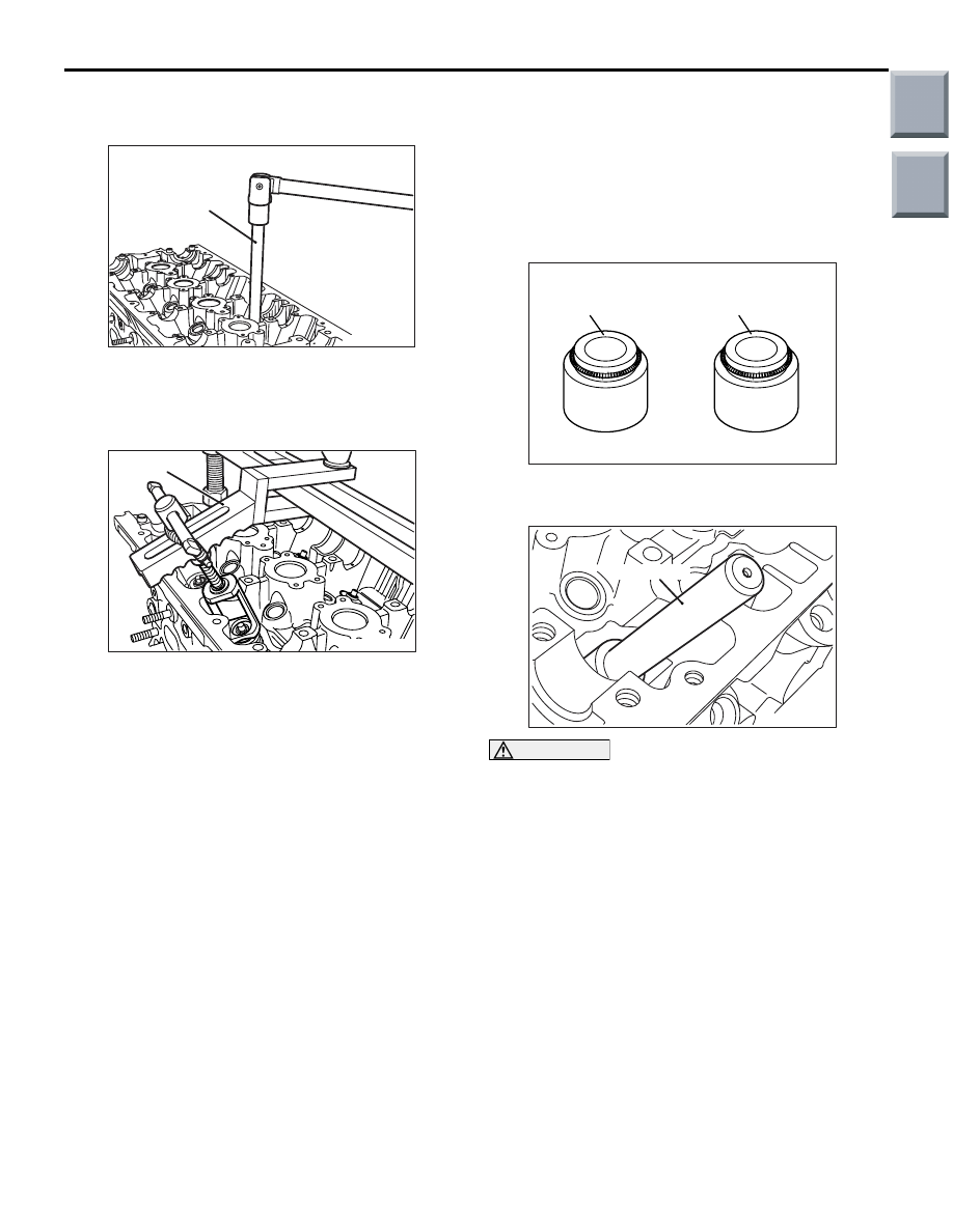
REMOVAL SERVICE POINTS
<<A>> CYLINDER HEAD BOLT REMOVAL
AK201787
MB991653
AC
Use the special tool Cylinder head bolt wrench
(MB991653) to loosen the cylinder head bolts.
<<B>> RETAINER LOCK REMOVAL
AK201789
MD998772
AC
Compress the valve spring using the special tool
Valve spring compressor (MD998772), then remove
the retainer lock.
NOTE: Store removed valves, springs and other
parts, after putting to each of them a tag that identi-
fies its cylinder No. or installation location.
INSTALLATION SERVICE POINTS
>>A<< VALVE STEM SEAL INSTALLA-
TION
1. Install the valve spring seat.
2. Install the valve.
3. Apply a thin coat of engine oil to a new valve stem
seal.
AK302994AC
Exhaust valve stem seal
Colour: Grayish green
Intake valve stem seal
Colour: Gray
NOTE: Do not confuse the stem seals for intake
valves with those for exhaust valves.
AK201791AC
MB991671
CAUTION
• Do not reuse the valve stem seal.
• The special tool must always be used when
installing the valve stem seal. Improper instal-
lation could result in oil leaks past the valve
guide.
4. Use the special tool Valve seal installer
(MB991671) to install the stem seal on the valve
guide. Use the stem of the valve to guide the stem
seal.
Main
Index
Group
TOC

CYLINDER HEAD AND VALVES
ENGINE OVERHAUL <4G1>
11D-35
>>B<< VALVE SPRING INSTALLATION
AK300590AB
Spring
retainer
Stem
seal
Spring
seat
Painted
end
Install each valve spring with the painted end toward
the rocker arm.
>>C<< RETAINER LOCK INSTALLATION
AK201789
MD998772
AC
Compress the valve spring using the special tool
Valve spring compressor (MD998772), then install
the retainer lock.
>>D<< CYLINDER HEAD BOLT
INSTALLATION
AK300591AB
Shank length
1. When reusing a cylinder head bolt, check that its
nominal length (shank length) is not greater than
the limit. If the limit is exceeded, replace the bolt.
Limit: 103.2 mm
2. Apply engine oil to the threads and washer of the
bolt.
AK201788
MB991653
AC
NOTE: Use the special tool Cylinder head bolt
wrench (MB991653) to tighten the bolts.
AK304398
1
3
9
6
8
2
5
7
4
10
Timing belt side
AB
3. Tighten the bolts to 49
± 2 N⋅m in the indicated
sequence.
4. Loosen all the bolts completely.
5. Tighten the bolts again to a torque of 20
± 2 N⋅m
in the indicated sequence.
AK202720
Paint marks
90˚
90˚
AB
CAUTION
• If the tightening angle is smaller than 90°,
proper fastening performance could not be
assured. Be sure to respect that angle.
• If the bolt is tightened to an angle greater than
the specified angle, loosen the bolt com-
pletely and then retighten it beginning with
the first step.
6. Make paint marks on each bolt’s head and on the
cylinder head.
7. Turn the bolts 90
° in the tightening direction and
in the indicated sequence.
Main
Index
Group
TOC
Нет комментариевНе стесняйтесь поделиться с нами вашим ценным мнением.
Текст