Mitsubishi Colt Ralliart. Manual — part 609

CYLINDER HEAD AND VALVES
ENGINE OVERHAUL <4G1>
11D-36
8. Give another 90
° turn in the tightening direction to
each bolt, making sure that the paint mark on the
bolt head and that on the cylinder head are on the
same line.
INSPECTION
M1113007000873
CYLINDER HEAD
1. Before cleaning the cylinder head, check it for
traces of water and gas leakage and for cracks
and any other damage.
2. Thoroughly remove oils, scale, sealants, carbon
and other contamination. Clean the oil passages,
then check using compressed air that they are not
blocked.
AK202724
3. Check the cylinder head gasket surface for warp
using a straightedge and thickness gauge.
If the surface is warped beyond the limit, grind the
surface for rectification.
CAUTION
The thickness of the metal that can be removed
by grinding from both the cylinder head and the
mating cylinder block is limited to 0.2 mm in
total.
Gasket surface warp
Standard value: 0.03 mm or less
Limit: 0.2 mm
Grinding limit: 0.2 mm
Cylinder head height (standard value for new
part):
131.9
− 132.1 mm
VALVES
1. Check the valve face for correct contact with the
seat. Reface the valve if the contact is partial or
one sided.
AK300593AB
Margin
Contact
(Should be at
centre of face)
2. Measure the margin.
Replace the valve if its margin is smaller than the
limit.
Standard values:
Intake 1.0 mm
Exhaust 1.5 mm
Limits:
Intake 0.5 mm
Exhaust 1.0 mm
AK304590AB
Total length
3. Measure the total length of the valve.
Replace the valve if the length is less than the
limit.
Standard values:
Intake 106.35 mm
Exhaust 106.85 mm
Limits:
Intake 105.85 mm
Exhaust 106.35 mm
Main
Index
Group
TOC
CYLINDER HEAD AND VALVES
ENGINE OVERHAUL <4G1>
11D-37
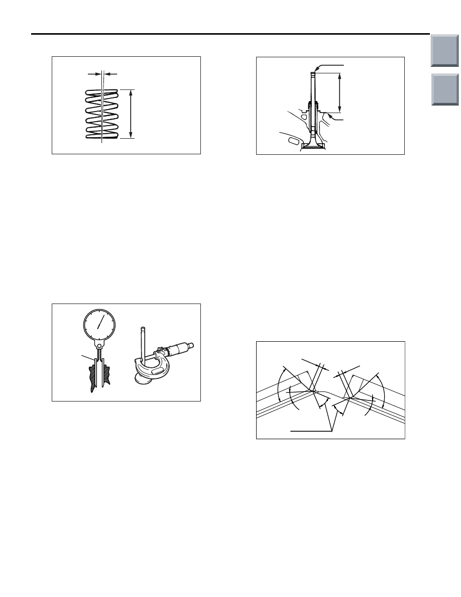
VALVE SPRINGS
AK300594
Out of square
Free height
AB
1. Measure the free height of the spring.
Replace the spring if its height is smaller than the
limit.
Standard value: 54.8 mm
Limit:53.8 mm
2. Measure the squareness of the spring.
Replace the spring if it is out of square beyond the
limit.
Standard value: 2
° or less
Limit: 4
°
VALVE GUIDE
AK300168
Guide inside diameter
Stem diameter
Valve
guide
AE
Measure the valve guide inside diameter and valve
stem diameter to calculate the clearance between
the valve guide and valve stem.
If the limit is exceeded, replace the valve guide or
valve, or both.
Standard values:
Intake 0.02
− 0.05 mm
Exhaust 0.03
− 0.06 mm
Limits:
Intake 0.10 mm
Exhaust 0.15 mm
VALVE SEATS
AK300596
Valve stem
projection
Spring
seating
surface
AB
Valve stem
end
With the valve installed in position and its face
pressed against the valve seat, measure the valve
stem projection (distance between the valve stem
end and spring seating surface). If the measurement
exceeds the limit, replace the valve seat.
Standard values:
Intake 48.8 mm
Exhaust 48.7 mm
Limits:
Intake 49.3 mm
Exhaust 49.2 mm
VALVE SEAT RECONDITIONING
1. Before reconditioning the valve seat, check the
clearance between the valve guide and valve
stem and, if necessary, replace the valve guide.
AK201838AC
65˚
65˚
0.9 – 1.3 mm
0.9 – 1.3 mm
20˚
15˚
43.5˚ to 44˚
Intake valve stem seal
Exhaust valve stem seal
2. Resurface the valve seat to the indicated width
and angles.
3. After resurfacing, lap the valve and valve seat
using lapping compound.
Main
Index
Group
TOC

CYLINDER HEAD AND VALVES
ENGINE OVERHAUL <4G1>
11D-38
VALVE SEAT REPLACEMENT
AK300597
0.5 – 1 mm
0.5 – 1 mm
Cut
AB
1. Cut inside of the valve seat to be replaced until its
wall becomes thin enough for removal, then
remove the valve seat.
AK300598
Valve seat
height
Oversize hole diameter
AB
2. Rebore the valve seat hole in the cylinder head to
a diameter matched to the diameter of the
selected oversize valve seat.
Intake valve seat hole diameters:
0.3 oversize 31.30
− 31.33 mm
0.6 oversize 31.60
− 31.63 mm
Exhaust valve seat hole diameters:
0.3 oversize 27.80
− 27.82 mm
0.6 oversize 28.10
− 28.12 mm
3. Before fitting the valve seat, cool it in liquid
nitrogen to prevent damage to its hole in the
cylinder head due to interference.
4. Resurface the valve seat. See the VALVE SEAT
RECONDITIONING section.
VALVE GUIDE REPLACEMENT
1. Force out the valve guide toward the cylinder
block using a press.
CAUTION
Do not use a replacement valve guide of the
same size as the removed one.
2. Machine the valve guide hole in the cylinder head
to the size matched to the selected oversize valve
guide.
Valve guide hole diameters
0.05 oversize: 10.55
− 10.57mm
0.25 oversize: 10.75
− 10.77 mm
0.50 oversize: 11.00
− 11.02 mm
AK201837AC
Projection
3. Press-fit the valve guide until it remains protruded
above the cylinder head by the amount indicated
in the illustration.
Standard value: 22.7
− 23.3 mm
NOTE: Press the valve guide from above the cyl-
inder head.
NOTE: The valve guides for the intake valves are
different in length from those for the exhaust
valves (48 mm for intake valves; 55 mm for
exhaust valves)
4. After installing the valve guide, insert a new valve
in it to check for smooth movement.
Main
Index
Group
TOC

OIL PAN AND OIL PUMP
ENGINE OVERHAUL <4G1>
11D-39
OIL PAN AND OIL PUMP
REMOVAL AND INSTALLATION
M1113008101241
AK401832AD
Apply engine oil to
all moving parts
before installation.
10
18
19
12
14
16
13
9
7
20
4
5
8
23 ± 4 N·m
39 ± 5 N·m
7.0 ± 1.0 N·m
10 ± 2 N·m
11
6
17
10 ± 2 N·m
14 ± 1 N·m
19 ± 3 N·m
44 ± 5 N·m
10 ± 2 N·m
15
3
2
1
27 ± 2 N·m
AK401832
Removal steps
>>
F
<< 1. Oil filter
2. Oil cooler bolt
3. Oil cooler
>>
E
<< 4. Oil pressure switch
>>
D
<< 5. Drain plug
6. Drain plug gasket
7. Transmission stay
<<
A
>> >>
C
<< 8. Oil pan
9. Oil screen
10. Oil screen gasket
11. Baffle plate
12. Relief plug
13. Relief spring
14. Relief plunger
>>
B
<< 15. Front oil seal
>>
A
<< 16. Oil pump case
17. O-ring
18. Oil pump cover
19. Oil pump outer rotor
20. Oil pump inner rotor
Removal steps (Continued)
Main
Index
Group
TOC
Нет комментариевНе стесняйтесь поделиться с нами вашим ценным мнением.
Текст