Honda Ridgeline. Manual — part 313
SJC8A00K79700081810FAAT00
SJC8A00K79700081830FAAT02
−
−
−
−
−
−
−
−
−
−
DTC 81:
DTC 83:
YES
NO
YES
NO
YES
NO
YES
NO
YES
NO
18-77
18-77
TPMS Control Unit Failure
No VSP Signal
NOTE: Low battery voltage can cause this DTC. Make
sure the battery is fully charged and in good condition.
1. Turn the ignition switch ON (II).
2. Clear the DTC with the HDS.
3. Turn the ignition switch OFF, then turn it ON (II)
again.
4. Check for DTCs with the HDS.
Replace the TPMS control unit (see page
18-84).
The system is OK at this time.
1. Turn the ignition switch ON (II).
2. Clear the DTC with the HDS.
3. Test-drive the vehicle.
4. Check for DTCs with the HDS.
Go to step 5.
The system is OK at this time.
5. Check for DTCs with the HDS.
Go to DTC 85 troubleshooting (see page
18-78).
Go to step 6.
6. Test-drive the vehicle.
7. Check the VEHICLE SPEED in the TPMS DATA LIST
with the HDS.
Check for loose terminals and poor
connections at the TPMS control unit. If necessary,
substitute a known-good TPMS control unit
(see page 18-84), and recheck.
Go to step 8.
8. Check the speedometer.
Replace the TPMS control unit (see page
18-84).
Substitute a known-good PCM (see page 11-8),
and retest. If no codes are shown, replace the
original PCM.
Is DT C 81 indicated?
Is DT C 83 indicated?
Is DT C 85 indicated?
Is the vehicle speed indicated?
Does the speedometer r egister speed?
01
SJC8A00K79700081850FAAT00
−
−
−
−
−
−
−
−
DTC 85:
YES
NO
YES
NO
YES
NO
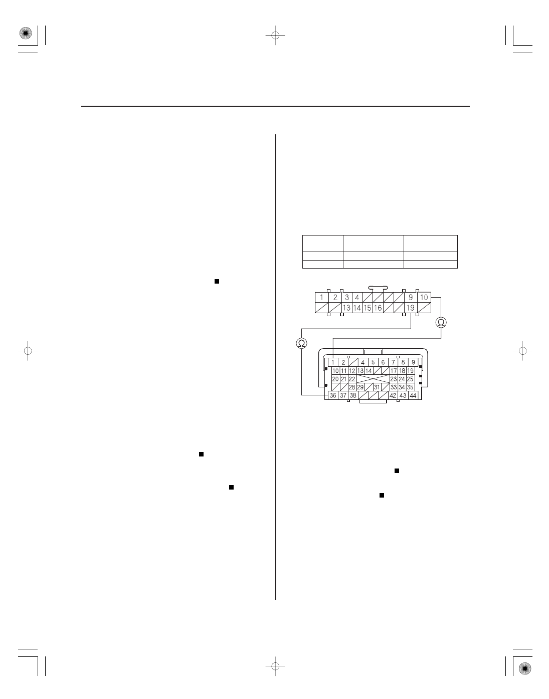
Terminal
name
TPMS control
unit terminal
PCM A
terminal
YES
NO
18-78
TPMS
DTC Troubleshooting (cont’d)
TPMS CONTROL UNIT CONNECTOR B (20P)
CAN H
(WHT)
PCM CONNECTOR A (44P)
CAN L
(RED)
F-CAN Communication Failure
1. Turn the ignition switch ON (II).
2. Clear the DTC with the HDS.
3. Turn the ignition switch OFF, then turn the ignition
switch ON (II) again.
4. Wait about 5 seconds.
5. Check for DTCs with the HDS.
Go to step 6.
The system is OK at this time.
6. Test-drive the vehicle.
Go to step 10.
Go to step 7.
7. Turn the ignition switch OFF.
8. Disconnect the TPMS control unit connector B (20P).
9. Test-drive the vehicle.
Check for loose terminals and poor
connections at the TPMS control unit. If necessary,
substitute a known-good TPMS control unit
(see page 18-84), and recheck.
Turn the ignition switch OFF, and reconnect
all connectors, then check and troubleshoot the fuel
and emissions systems (see page 11-3).
10. Turn the ignition switch OFF.
11. Short the SCS line with the HDS.
12. Disconnect PCM connector A (44P).
13. Disconnect the TPMS control unit connector B (20P).
14. Check for continuity between the TPMS control unit
connector B (20P) terminals and the PCM connector
A (44P) terminals individually (see table).
CAN L
No. 10
No. 1
CAN H
No. 19
No. 36
Check for loose terminals and poor
connections at the TPMS control unit. If necessary,
substitute a known-good TPMS control unit
(see page 18-84), and recheck.
Repair open in the wire between the TPMS
control unit and the PCM.
Wire side of female terminals
Terminal side of female terminals
Is DT C 85 indicated?
Does the speedometer wor k?
Does the speedometer wor k?
Is ther e continuity?
SJC8A00K79700081910FAAT00
−
−
DTC 91, 93, 95, 97:
DTC
Tire location
YES
NO
18-79
Tire Pressure Sensor
Internal Error
1. Turn the ignition switch ON (II).
2. Clear the DTC with the HDS.
3. Turn the ignition switch OFF, then turn it ON (II)
again.
4. Wait about 1 minute.
5. Check for DTCs with the HDS.
NOTE: The tire pressure sensor of the appropriate
wheel is shown.
91
Right-front
93
Left-front
95
Right-rear
97
Left-rear
Replace the appropriate tire pressure sensor
(see page 18-86).
The system is OK at this time.
Is DT C 91, 93, 95 or 97 indicated?
01
SJC8A00B54175137672FAAT02
−
−
−
−
−
−
−
−
−
−
Low tire pressure and tire indicators do not
come on, and no DTCs are stored
YES
NO
YES
NO
YES
NO
YES
NO
YES
NO
18-80
TPMS
Symptom Troubleshooting
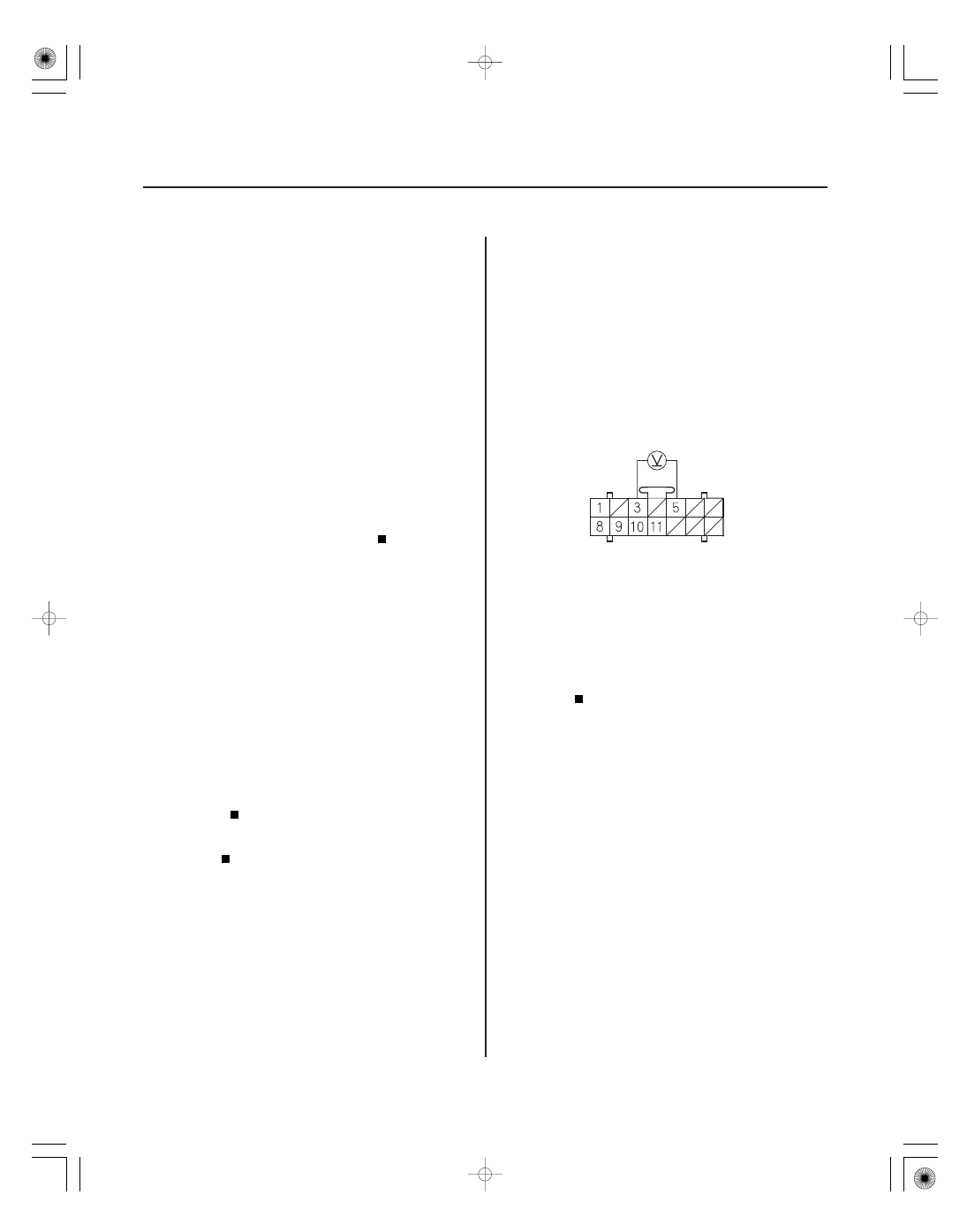
TPMS CONTROL UNIT CONNECTOR A (14P)
GND (BLK)
IG1 (YEL)
1. Turn the ignition switch ON (II), and watch the low
pressure indicator and the tire indicators.
Go to step 2.
Go to step 4.
2. Check the pressure in all four tires.
Go to step 3.
The system is OK at this time.
3. Connect the HDS and read the pressure of the low
tires.
NOTE: If UNDEFINED is shown on sensor
transmitter status, turn the ignition switch OFF,
rotate the appropriate tire 1/4 turn, then turn the
ignition switch ON (II), and try again. If there is still
no response, repeat the procedure in the previous
sentence until a response is shown.
Check for loose terminals and poor
connections at the TPMS control unit. If necessary,
substitute a known-good TPMS control unit and
recheck.
Replace the tire pressure sensor (see page
18-86).
4. Connect the HDS and select TPMS.
Go to step 9.
Go to step 5.
5. Measure the voltage between the TPMS control
unit connector A (14P) terminals No. 3 and No. 5.
Check for loose terminals and poor
connections at the TPMS control unit. If necessary,
substitute a known-good TPMS control unit and
recheck.
Go to step 6.
6. Turn the ignition switch OFF, then disconnect the
TPMS control unit connector A (14P).
Wire side of female terminals
Do the low tir e pr essur e and indicator s come on
f or at least 2 seconds?
Is the tir e pr essur e 168 kPa ( 1.7 kgf / cm , 24 psi)
or less?
Is the tir e pr essur e shown on the HDS monitor
within 40 kPa ( 0.4 kgf / cm , 6 psi) of the actual tir e
pr essur e?
Does the HDS communicate with the T PMS
contr ol unit?
Is ther e batter y voltage?
2
2
Нет комментариевНе стесняйтесь поделиться с нами вашим ценным мнением.
Текст