Honda Ridgeline. Manual — part 312
SJC8A00K79700081510FAAT00
−
−
−
−
DTC 51, 53, 55, 57:
DTC
Tire location
YES
NO
DTC
Tire location
YES
NO
18-73
Tire Pressure Sensor
Registration Error
NOTE: These DTCs will only set during initialization
with the HDS.
1. Check the DTC indicated to the tire location to
make sure the wheel is a TPMS type with the tire
pressure sensor.
51
Right-front
53
Left-front
55
Right-rear
57
Left-rear
Go to step 7.
Go to step 2.
2. Install a known-good TPMS wheel.
3. To memorize the sensor ID, drive the vehicle above
15 mph (24 km/h) for 40 continuous seconds, or
memorize the ID with the HDS (see page 18-51).
4. Turn the ignition switch OFF.
5. Turn the ignition switch ON (II).
6. With the HDS, check the indicated tire for the
normal sensor signal.
NOTE: If the HDS screen shows UNDEFINED for
sensor status, turn the ignition switch OFF, rotate
the tire 1/4 turn, then turn the ignition switch ON (II),
and try again. If UNDEFINED is still shown, repeat
the procedure in the previous sentence until
NORMAL is shown.
51
Right-front
53
Left-front
55
Right-rear
57
Left-rear
The system is OK at this time. Clear the DTC
with the HDS.
Go to step 12.
7. Turn the ignition switch OFF.
8. Install a wheel with a known-good tire pressure
sensor on the vehicle.
9. To memorize the sensor ID, drive the vehicle above
15 mph (24 km/h) for 40 continuous seconds, or
memorize the ID with the HDS (see page 18-51).
10. Turn the ignition switch OFF.
11. Turn the ignition switch ON (II).
(cont’d)
Is a T PMS type wheel with a tir e pr essur e sensor
mounted on the vehicle?
Is NORMAL indicated within one f ull tur n of the
tir e?
*01
−
−
−
−
DTC
Tire location
YES
NO
DTC
Initiator location
DTC
TPMS control
unit terminal
Initiator name/
terminal No.
YES
NO
18-74
TPMS
DTC Troubleshooting (cont’d)
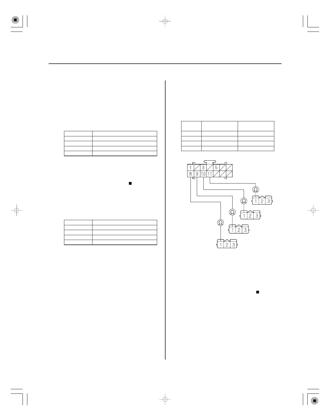
TPMS CONTROL UNIT CONNECTOR A (14P)
RR LF PWR. (BLU)
RIGHT-REAR
LEFT-REAR
RIGHT-FRONT
LEFT-FRONT
LR LF PWR. (GRN/BLU)
RF LF PWR. (BLU)
LF LF PWR. (YEL/BLU)
INITIATOR 3P CONNECTOR
12. With the HDS, check the indicated tire for a normal
pressure sensor signal.
NOTE: If the HDS screen shows UNDEFINED for
sensor status, turn the ignition switch OFF, rotate
the tire 1/4 turn, then turn the ignition switch ON (II),
and try again. If UNDEFINED is still shown, repeat
the procedure in the previous sentence until
NORMAL is shown.
51
Right-front
53
Left-front
55
Right-rear
57
Left-rear
Replace the tire pressure sensor on the
customer’s wheel (see page 18-86).
Go to step 13.
13. Turn the ignition switch OFF.
14. Disconnect the appropriate initiator 3P connector.
51
Right-front
53
Left-front
55
Right-rear
57
Left-rear
15. Disconnect the TPMS control unit connector A (14P)
and B (20P).
16. Check for continuity between the appropriate
terminal in TPMS control unit connector A (14P)
terminal and appropriate initiator 3P connector
terminal No. 1 (see table).
51
No. 9
RIGHT-FRONT/1
53
No. 8
LEFT-FRONT/1
55
No. 11
RIGHT-REAR/1
57
No. 10
LEFT-REAR/1
Go to step 17.
Repair open in the wire between the TPMS
control unit and the appropriate initiator.
Wire side of
female terminals
Wire side of
female terminals
Is NORMAL indicated within one f ull tur n of the
tir e?
Is ther e continuity?
*02
*03
−
−
−
−
DTC
TPMS control
unit terminal
Initiator name/
terminal No.
YES
NO
DTC
TPMS control
unit terminal
Initiator name/
terminal No.
YES
NO
18-75
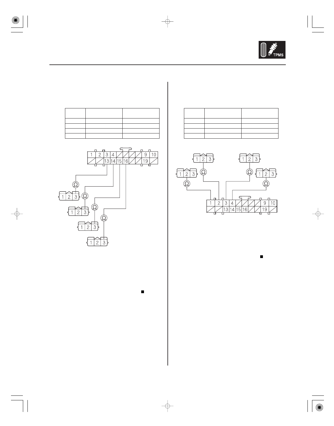
TPMS CONTROL UNIT CONNECTOR B (20P)
LR LF GND
(YEL/GRN)
RF LF GND
(RED/BLK)
LF LF GND
(GRN)
INITIATOR 3P CONNECTOR
RR LF GND
(RED/ORN)
LEFT-FRONT
RIGHT-FRONT
LEFT-REAR
RIGHT-REAR
RIGHT-FRONT
RIGHT-REAR
RF LF SIG.
(GRY/YEL)
RR LF SIG.
(GRY/YEL)
LF LF SIG.
(ORN)
LR LF SIG. (PNK/BLK)
LEFT-FRONT
LEFT-REAR
TPMS CONTROL UNIT CONNECTOR B (20P)
INITIATOR 3P CONNECTOR
17. Check for continuity between the appropriate
terminal in TPMS control unit connector B (20P)
and appropriate initiator 3P connector terminal
No. 3 (see table).
51
No. 14
RIGHT-FRONT/3
53
No. 13
LEFT-FRONT/3
55
No. 16
RIGHT-REAR/3
57
No. 15
LEFT-REAR/3
Go to step 18.
Repair open in the wire between the TPMS
control unit and the appropriate initiator.
18. Check for continuity between the appropriate
terminal in TPMS control unit connector B (20P)
and appropriate initiator 3P connector terminal
No. 2 (see table).
51
No. 1
RIGHT-FRONT/2
53
No. 3
LEFT-FRONT/2
55
No. 2
RIGHT-REAR/2
57
No. 4
LEFT-REAR/2
Go to step 19.
Repair open in the wire between the TPMS
control unit and the appropriate initiator.
(cont’d)
Wire side of
female terminals
Wire side of
female terminals
Wire side of
female terminals
Wire side of female terminals
Is ther e continuity?
Is ther e continuity?
04
*04
−
−
−
−
DTC
TPMS control unit terminal
YES
NO
DTC
TPMS control unit terminal
YES
NO
18-76
TPMS
DTC Troubleshooting (cont’d)
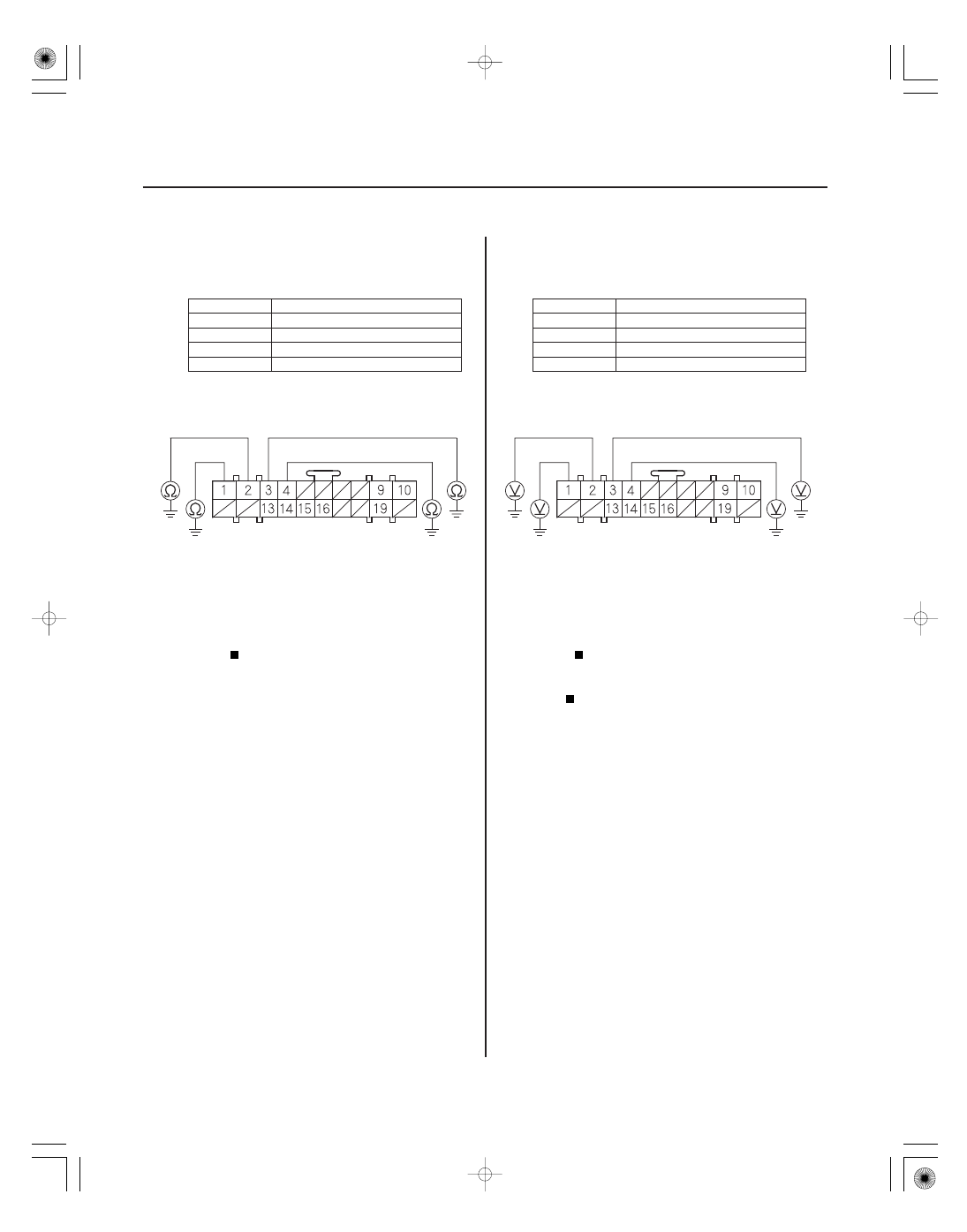
TPMS CONTROL UNIT CONNECTOR B (20P)
LF LF SIG. (ORN)
LR LF SIG. (PNK/BLK)
RR LF SIG.
(GRY/YEL)
RF LF SIG.
(GRY/YEL)
TPMS CONTROL UNIT CONNECTOR B (20P)
LF LF SIG. (ORN)
LR LF SIG. (PNK/BLK)
RR LF SIG.
(GRY/YEL)
RF LF SIG.
(GRY/YEL)
19. Check for continuity between body ground and the
appropriate TPMS control unit connector B (20P)
terminal (see table).
51
No. 1
53
No. 3
55
No. 2
57
No. 4
Repair short to body ground in the wire
between the TPMS control unit and the appropriate
initiator.
Go to step 20.
20. Measure the voltage between body ground and the
appropriate TPMS control unit connector B (20P)
terminal (see table).
51
No. 1
53
No. 3
55
No. 2
57
No. 4
Repair short to power in the wire between
the TPMS control unit and the appropriate
initiator.
Repair the appropriate initiator (see page
18-85).
Wire side of female terminals
Wire side of female terminals
Is ther e continuity?
Is ther e batter y voltage?
Нет комментариевНе стесняйтесь поделиться с нами вашим ценным мнением.
Текст