Acura RL (1996-2004 year). Manual — part 462
Differential Assembly
Removal
Make sure jacks and safety stands are placed properly,
and hoist brackets are attached to correct positions on
the engine.
Apply parking brake and block rear wheels so the
vehicle will not roll off stands and fall on you while
working under it.
CAUTION: Use fender covers to avoid damaging painted
surfaces.
1. Remove the drain plug, and drain the differential oil
).
2. Remove the cotter pins and castle nuts, than sepa-
rate the ball joints from the lower arm using the
special tool (see
).
3. Remove the right damper pinch bolt, then separate
the damper fork and damper (see
).
4. Pry the driveshafts out of the differential and inter-
CAUTION:
Do not pull on the driveshaft, as the inboard
joint may come apart.
Use care when prying out the assembly, and pull
it straight to avoid damaging the differential oil
seal or the intermediate shaft outer seal.
5. Pull on the inboard joint to remove the right drive-
shaft from the differential and to remove the left
driveshaft from the intermediate shaft (see
).
6. Remove the intermediate shaft assembly from the
).
7. Tie plastic bags over the driveshaft ends.
NOTE: Coat all precision finished surfaces with
clean engine oil.
SET RING
Replace.
PLASTIC BAG
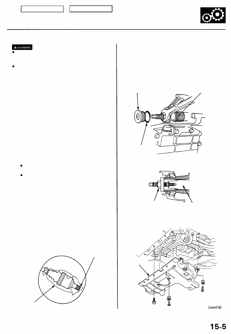
8. Remove the 36 mm sealing bolt and O-ring, then
disconnect the extension shaft from the differential
using the special tool.
NOTE: Shift the transmission into the B position to
lock the secondary gear.
36 mm SEALING
BOLT
SET RING
Replace.
O-RING
Replace.
EXTENSION SHAFT PULLER
or
EXTENSION SHAFT
9. Remove the splash shield.
SPLASH
SHIELD
Main Menu
Table of Contents
Differential Assembly
Removal (cont'd)
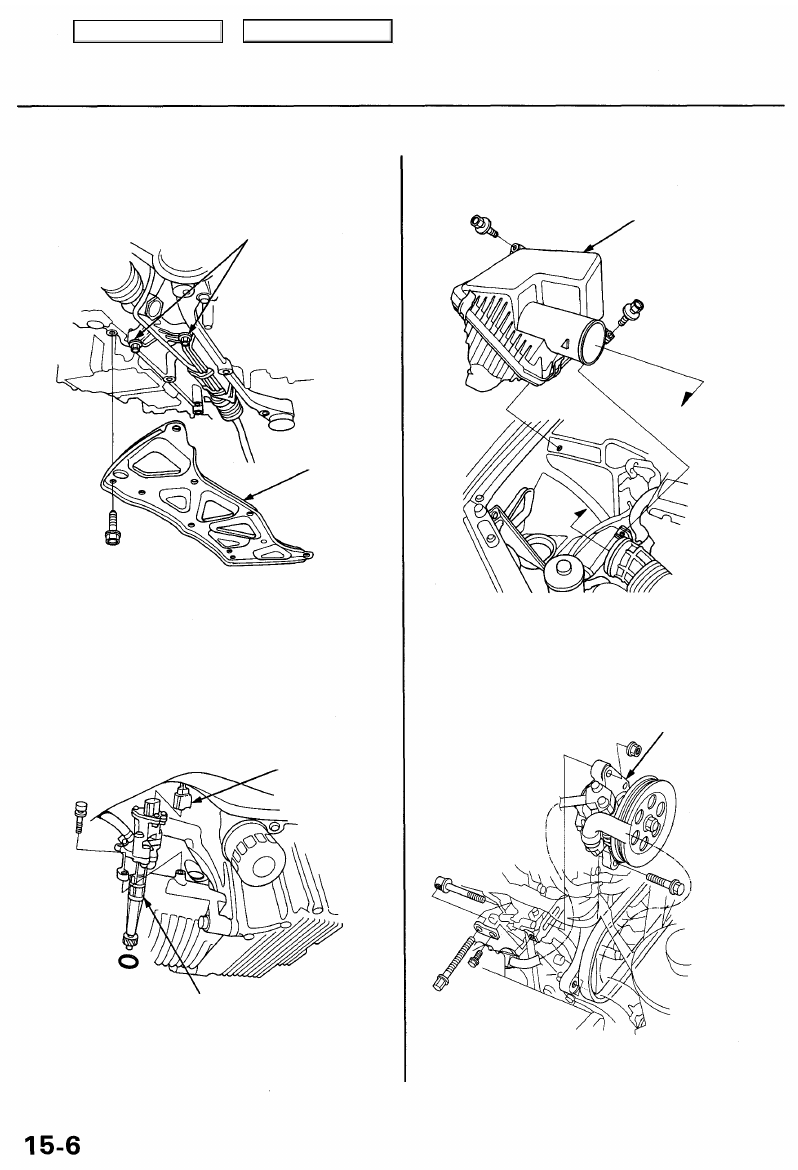
10. Remove the lower plate, then reinstall the steering
gearbox mounting bolts.
STEERING GEARBOX
MOUNTING BOLTS
59 N-m (6.0 kgf-m,
4.3 Ibf-ft)
LOWER PLATE
11. Disconnect the vehicle speed sensor (VSS) connec-
tor, then remove the VSS/power steering speed
sensor.
NOTE: Do not disconnect the hoses.
VSS CONNECTOR
VSS/POWER STEERING
SPEED SENSOR
12. Remove the air cleaner housing assembly.
AIR CLEANER
HOUSING ASSEMBLY
13. Remove the power steering pump.
NOTE: Do not disconnect the hoses.
POWER STEERING
PUMP
Main Menu
Table of Contents
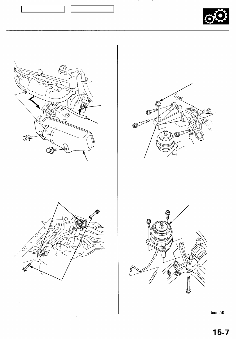
14. Disconnect the breather tube from the clamp, then
remove the right exhaust manifold cover.
CLAMP
BREATHER
TUBE
RIGHT EXHAUST
MANIFOLD COVER
15. Remove the engine stop mount bracket bolts.
ENGINE STOP
MOUNTS
ENGINE STOP
MOUNT BRACKET BOLTS
16. Attach the chain hoist to the engine (see
).
17. Remove the right and left engine mount bracket
nuts, then remove the right engine mount bracket.
ENGINE MOUNT
BRACKET NUT
RIGHT ENGINE
MOUNT BRACKET
18. Remove the right engine mount.
RIGHT ENGINE
MOUNT
Main Menu
Table of Contents
Differential Assembly
Removal (cont'd)
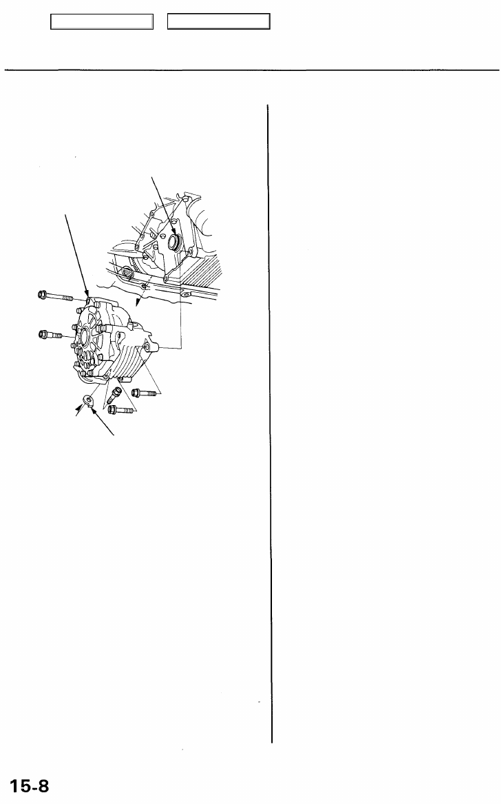
19. Remove the mounting bolts and 26 mm shim, then
remove the differential assembly.
O-RING
Replace.
DIFFERENTIAL
ASSEMBLY
26 mm SHIM
Main Menu
Table of Contents
Нет комментариевНе стесняйтесь поделиться с нами вашим ценным мнением.
Текст