Acura RL (1996-2004 year). Manual — part 460
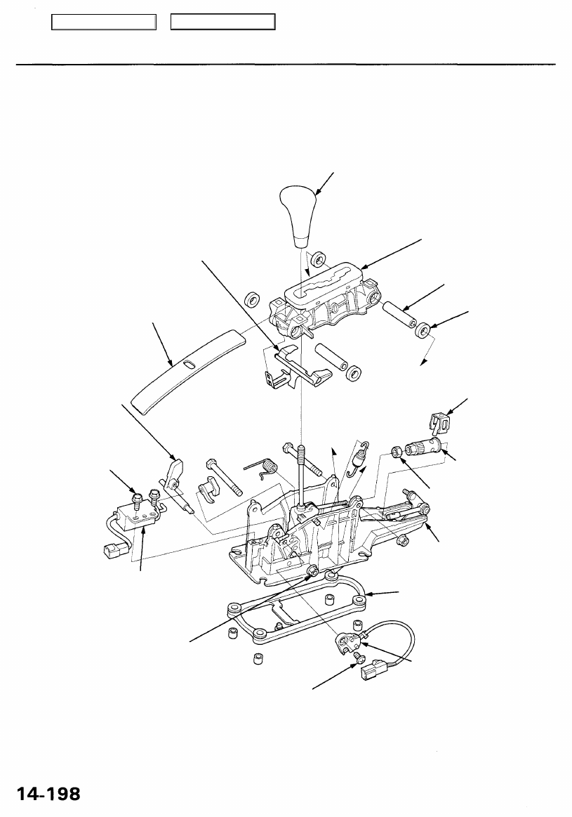
Shift Lever
Disassembly
SHIFT LOCK
RELEASE LEVER
LEVER COVER
SHIFT LOCK
STOP
6 x 1.0 mm
8 N-m (0.8 kgf-m,
6 Ibf-ft)
SHIFT LEVER KNOB
SHIFT LOCK SOLENOID
6x 1.0 mm
8 N-m (0.8 kgf-m, 6 Ibf-ft)
5 x 0.8 mm
4 N-m (0.4 kgf-m, 3 Ibf-ft)
A/T GEAR POSITION
PANEL
COLLAR
RUBBER
LOCK PIN
LINK ADJUSTER
LOCKNUT
7 N-m (0.7 kgf-m, 5 Ibf-ft
BRACKET BASE
PARK PIN SWITCH
CONTROL SEAL
Main Menu
Table of Contents
Link Adjustment
• Make sure lifts, jacks and safety stands are placed
).
• Apply parking brake, and block rear wheels so vehi-
cle will not roll off stands and fall on you while work-
ing under it.
1. Shift the transmission into the position.
2. Remove the center console (see
).
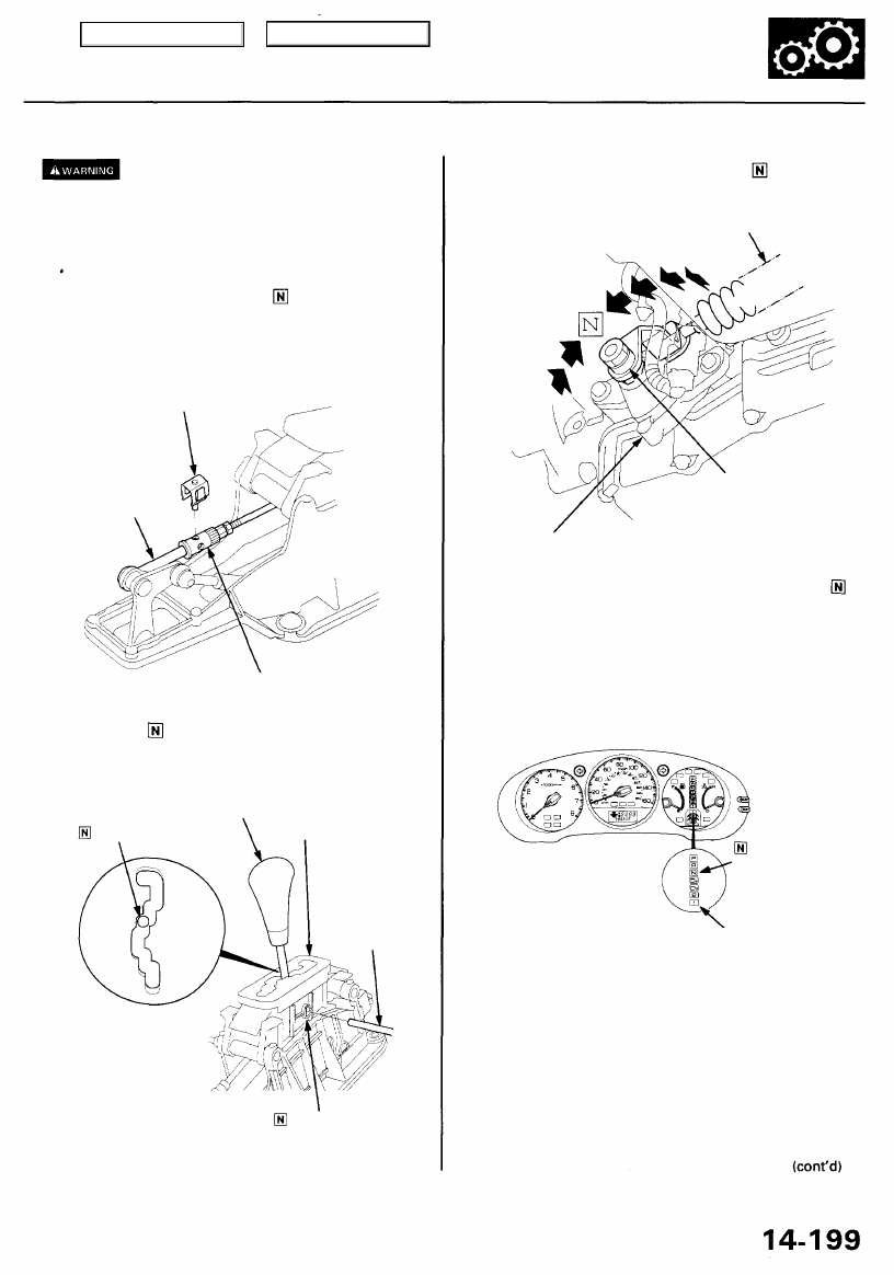
3. Remove the lock pin from the link adjuster.
LINK ROD
LINK ADJUSTER
4. Insert a 4.0 mm (0.16 in) pin into the shift lever bracket
through the position cutout of the shift lever.
CAUTION: Be sure to use a 4.0 mm (0.16 in) pin.
SHIFT LEVER
POSITION
A/T GEAR POSITION
PANEL
POSITION HOLE
5. Verify that the shift position is in the position on
the transmission.
SHIFT CABLE
CONTROL LEVER
A/T GEAR
POSITION SWITCH
6. Turn the ignition switch ON (II), verify that the
indicator light comes on.
CAUTION: Do not start the engine.
GAUGE ASSEMBLY
INDICATOR
LIGHT
A/T GEAR POSITION
INDICATOR
LOCK PIN
4.0 mm PIN
Main Menu
Table of Contents
Shift Lever
Link Adjustment (cont'd)
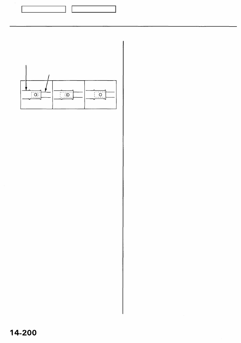
7. Check that the hole in the link adjuster is perfectly
aligned with the hole in the link rod.
LINK ADJUSTER
Link adjuster
Too Short
Link adjuster
Too Long
Exact
Alignment
NOTE: There are two holes in the link adjuster. They
are positioned 90° apart to allow link adjustments in
1/4 turn increments.
8 If not perfectly aligned, loosen the locknut on the
link adjuster, and adjust as required.
9. Tighten the locknut.
TORQUE: 7 N-m (0.7 kgf-m, 5 Ibf-ft)
10. Install the lock pin on the adjuster. If you feel the
lock pin binding as you reinstall it, the link rod is
still out of adjustment and must be readjusted.
11. Make sure the lock pin is seated securely in the
adjuster.
NOTE: Replace the lock pin if it does not snap over
the link adjuster securely.
12. Move the shift lever to each gear, and verify that the
A/T gear position indicator follows the transmission
range switch.
13. Start the engine, and check the shift lever in all
gears. If any gear does not work properly, refer to
troubleshooting on page
Install the center console (see
).
15. Insert the ignition key into the key cylinder on the
A/T gear position indicator panel, and verify that the
shift lock lever is released.
LINK ROD
Main Menu
Table of Contents
Shift Cable
Replacement
• Make sure lifts, jacks, and safety stands are placed
).
• Apply the parking brake, and block the rear wheels so
the vehicle will not roll off the stands and fall on you
while working under it.
1. Raise the front of the vehicle, and support it with
).
2. Set the parking brake, and block both rear wheels
securely.
3. Shift the transmission into the position.
4. Remove the center console (see
).
5. Shift the transmission into the position.
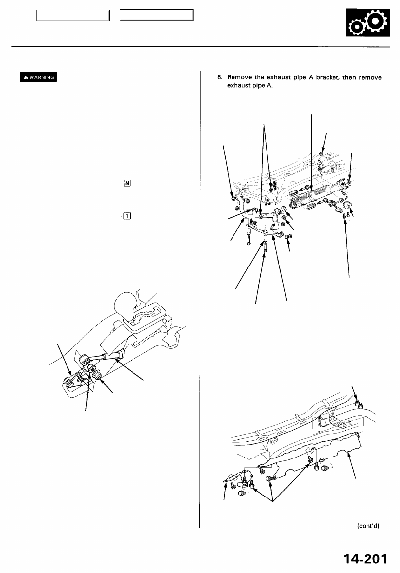
6. Remove the self-locking nut and shift cable end col-
lar, then remove the shift cable from the shift lever
link.
CAUTION: Take care not to bend the shift cable.
SHIFT LEVER
LINK
SHIFT CABLE
SELF-LOCKING NUT
9.8 N-m (1.0 kgf-m, 7.2 Ibf-ft)
SHIFT CABLE
END COLLAR
7. Pull the carpet back to expose the secondary HO2S
connector. Disconnect the connector, then push it to
outside.
NOTE: The secondary HO2S connector is located
under the passenger's seat.
BAND
EXHAUST
PIPE A
TRANSMISSION
STOP COLLAR
10 x 1.25mm
38 N-m
(3.9 kgf-m, 28 Ibf-ft)
SECONDARY
HO2S
HARNESS
COVER
6 x 1.0 mm
9.8 N-m (1.0 kgf-m,
7.2 Ibf-ft)
EXHAUST
PIPE A BRACKET
9. Remove the secondary HO2S harness cover, then
remove the three way catalytic converter.
10. Remove the heat shields.
6 x 1.0 mm
9.8 N-m (1.0 kgf-m,
7.2 Ibf-ft)
HEAT
SHIELD
6 x 1.0 mm
9.8 N-m (1.0 kgf-m,
7.2 Ibf-ft)
HEAT
SHIELD
8 x 1.25mm
22 N-m (2.2 kgf-m,
16 Ibf-ft)
THREE WAY
CATALYTIC
CONVERTER
10 x 1.25 mm
33 N-m (3.4 kgf-m,
25 Ibf-ft)
GASKET
Replace.
lOx 1.25 mm
54 N-m (5.5 kgf-m,
40 Ibf-ft)
GASKET
Replace.
8 x 1.25 mm
22 N-m (2.2 kgf-m,
16 Ibf-ft)
10x 1.25mm
33 N-m (3.4 kgf-m,
25 Ibf-ft)
Main Menu
Table of Contents
Нет комментариевНе стесняйтесь поделиться с нами вашим ценным мнением.
Текст