Acura RL (1996-2004 year). Manual — part 430
Troubleshooting Flowchart — Indicator Light On Constantly
The indicator light is on con-
stantly (not blinking) whenever
the ignition switch is ON (II).
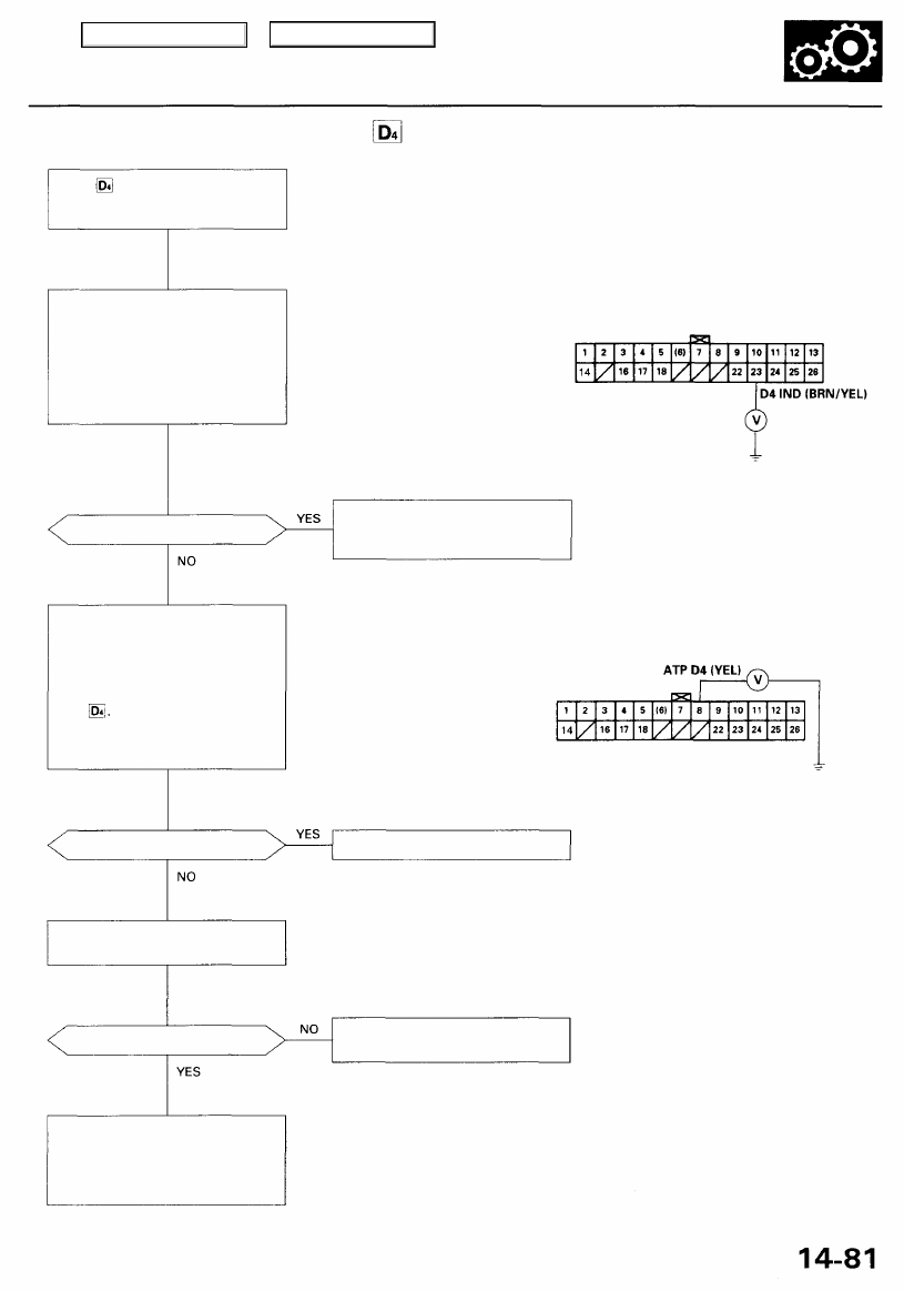
Measure D4 IND Voltage:
1. Turn the ignition switch OFF.
2. Disconnect the E (26P) con-
nector from the PCM.
3. Turn the ignition switch ON (II).
4. Measure the voltage between
the E23 terminal and body
ground.
Is there voltage?
Measure ATP D4 Voltage:
1. Turn the ignition switch OFF.
2. Connect the E (26P) connector
to the PCM.
3. Turn the ignition switch ON (II).
4. Shift to any position other than
5. Measure the voltage between
the E8 terminal and body
ground.
Is there voltage?
Test the transmission range
switch (see page
).
Is the switch OK?
Check for a short to ground in the
wire between the E8 terminal and
the transmission range switch. If
the wire is OK, substitute a
known-good PCM and recheck.
PCM CONNECTOR E (26P)
Wire side of female terminals
Repair short to power in the wire
between the E23 terminal and
the gauge assembly.
Replace the PCM.
Replace the transmission range
switch.
Main Menu
Table of Contents
Electrical Troubleshooting
Troubleshooting Flowchart — Interlock System - Shift Lock System
Inspection of the shift lock sys-
tem.
Check Brake Light Operation:
Press the brake pedal.
Are the brake lights ON?
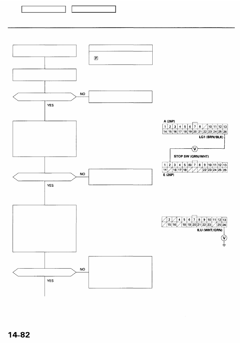
Measure STOP SW Voltage:
1. Turn the ignition switch OFF.
2. Disconnect the A (26P) and
E (26P) connectors from the
PCM.
3. Measure the voltage between
the E2 and A26 terminals with
the brake pedal pressed.
Is there battery voltage?
Is there battery voltage?
Possible Cause
Shift lever cannot be moved from
position with the brake pedal
pressed.
Repair faulty brake pedal position
switch circuit (see
).
Repair open in the wire between
the E2 terminal and the brake
pedal position switch.
Check open or short in the wire
between the A26 terminal of the
multiplex control unit (driver's) and
the E22 terminal of the PCM. If
wire is OK, check for loose PCM
connectors. If necessary, substitute
a known-good PCM and recheck.
PCM CONNECTORS
Wire side of female terminals
MULTIPLEX CONTROL UNIT (DRIVER'S)
A (26P) CONNECTOR
Wire side of female terminals
Measure ILU Voltage:
1. Connect the A (26P) and E
(26P) connectors to the PCM.
2. Disconnect the A (26P) and
B (16P) connectors from the
multiplex control unit (driver's).
3. Turn the ignition switch ON (II).
4. Measure the voltage between
the A26 terminal and body
ground with the brake pedal
pressed.
Main Menu
Table of Contents
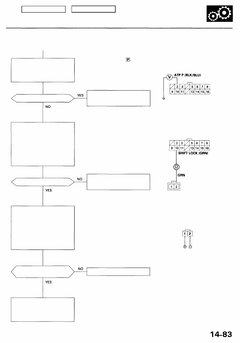
Measure ATP P Voltage:
Measure the voltage between the
B2 terminal of the multiplex con-
trol unit (driver's) and body
ground.
NOTE: Shift lever must be in
MULTIPLEX CONTROL UNIT (DRIVER'S)
B (16P) CONNECTOR
Is there voltage?
Check Shift Lock Solenoid for a
Open Circuit:
1. Turn the ignition switch OFF.
2. Disconnect the shift lock sole-
noid connector.
3. Check for continuity between
the B10 terminal of the multi-
plex control unit (driver's) and
the No. 2 terminal of the shift
lock solenoid connector.
Is there continuity?
Does the shift lock solenoid
operate properly?
Check for loose multiplex control
unit (driver's) connectors. If nec-
essary, substitute a known-good
multiplex control unit (driver's)
and recheck.
Repair open in the wire between
the B2 terminal and the transmis-
sion range switch.
Wire side of female terminals
MULTIPLEX CONTROL UNIT (DRIVER'S)
B (16P) CONNECTOR
Wire side of
female terminals
Repair open in the wire between
the B10 terminal and the shift lock
solenoid.
NOTE: Do not connect the No. 2 terminal to
the battery positive terminal or you will
damage the diode inside the shift lock
solenoid.
SHIFT LOCK SOLENOID
2P CONNECTOR
Terminal side of male terminals
SHIFT LOCK SOLENOID
2P CONNECTOR
Wire side of female terminals
Replace the shift lock solenoid.
Check Shift Lock Solenoid Oper-
ation:
1. Connect the No. 1 terminal of
the shift lock solenoid connec-
tor to the battery positive ter-
minal, and connect the No. 2
terminal to the battery nega-
tive terminal.
2. Check the shift lock solenoid
operation.
Main Menu
Table of Contents
Electrical Troubleshooting
Troubleshooting Flowchart — Interlock System — Key Interlock System
Inspection of the key interlock sys-
tem.
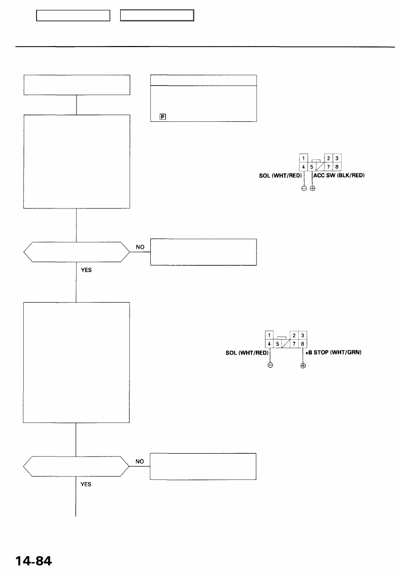
Check Key Interlock Solenoid
Operation:
1. Disconnect the ignition switch
connector (8P).
2. Connect the No. 5 terminal of
the ignition switch connector to
the battery positive terminal,
and connect the No. 4 termi-
nal to the battery negative ter-
minal.
3. Check the key interlock solenoid
operation. A clicking sound
should be heard.
Does the key interlock
solenoid operate properly?
Check Key Interlock Switch Oper-
ation:
1. Connect the No. 8 terminal of
the ignition switch connector
to the battery positive termi-
nal, and connect the No. 4 ter-
minal to the battery negative
terminal.
2. Turn the ignition switch to
ACC (I), then push it.
3. Check the key interlock solenoid
operation. A clicking sound
should be heard while push-
ing the ignition key, and no
sound should be heard when
releasing the ignition key.
Does the key interlock
solenoid operate properly?
Possible Cause
Ignition key cannot be moved
from ACC (I) position to LOCK (0)
position while pushing the igni-
tion key with the shift lever is in
position.
IGNITION SWITCH 8P CONNECTOR
Wire side of female terminals
Faulty the key interlock solenoid.
Replace the ignition key cylinder/
steering lock assembly.
Faulty the key interlock switch.
Replace the ignition key cylinder/
steering lock assembly.
Main Menu
Table of Contents
Нет комментариевНе стесняйтесь поделиться с нами вашим ценным мнением.
Текст