Acura RL (1996-2004 year). Manual — part 428
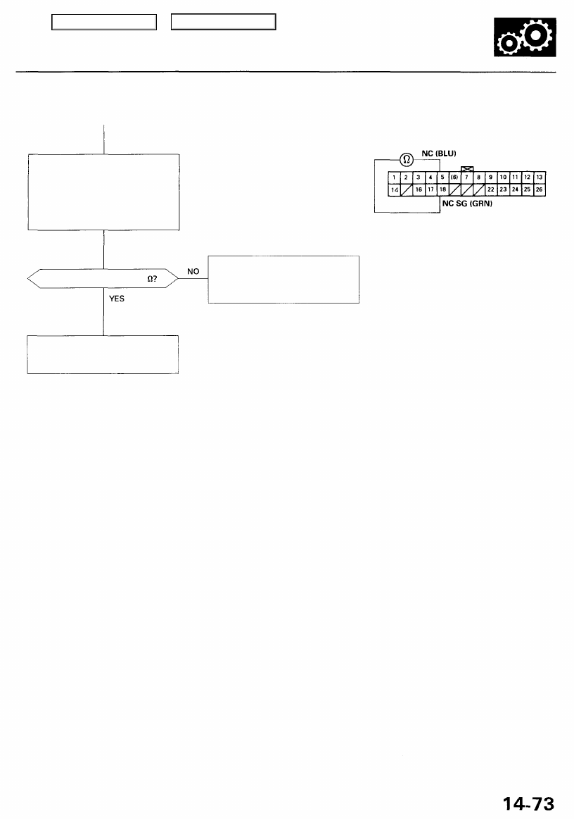
PCM CONNECTOR E (26P)
Measure Countershaft Speed
Sensor Resistance:
1. Connect the c o u n t e r s h a f t
speed sensor 3P connector.
2. Measure the resistance
between the E5 and E18 ter-
minals.
Wire side of female terminals
Is the resistance 400 - 600
Repair loose terminal or open in
the wires between the E5 and
E18 terminals and the counter-
shaft speed sensor.
Check for loose PCM connectors.
If necessary, substitute a known-
good PCM and recheck.
Main Menu
Table of Contents
Electrical Troubleshooting
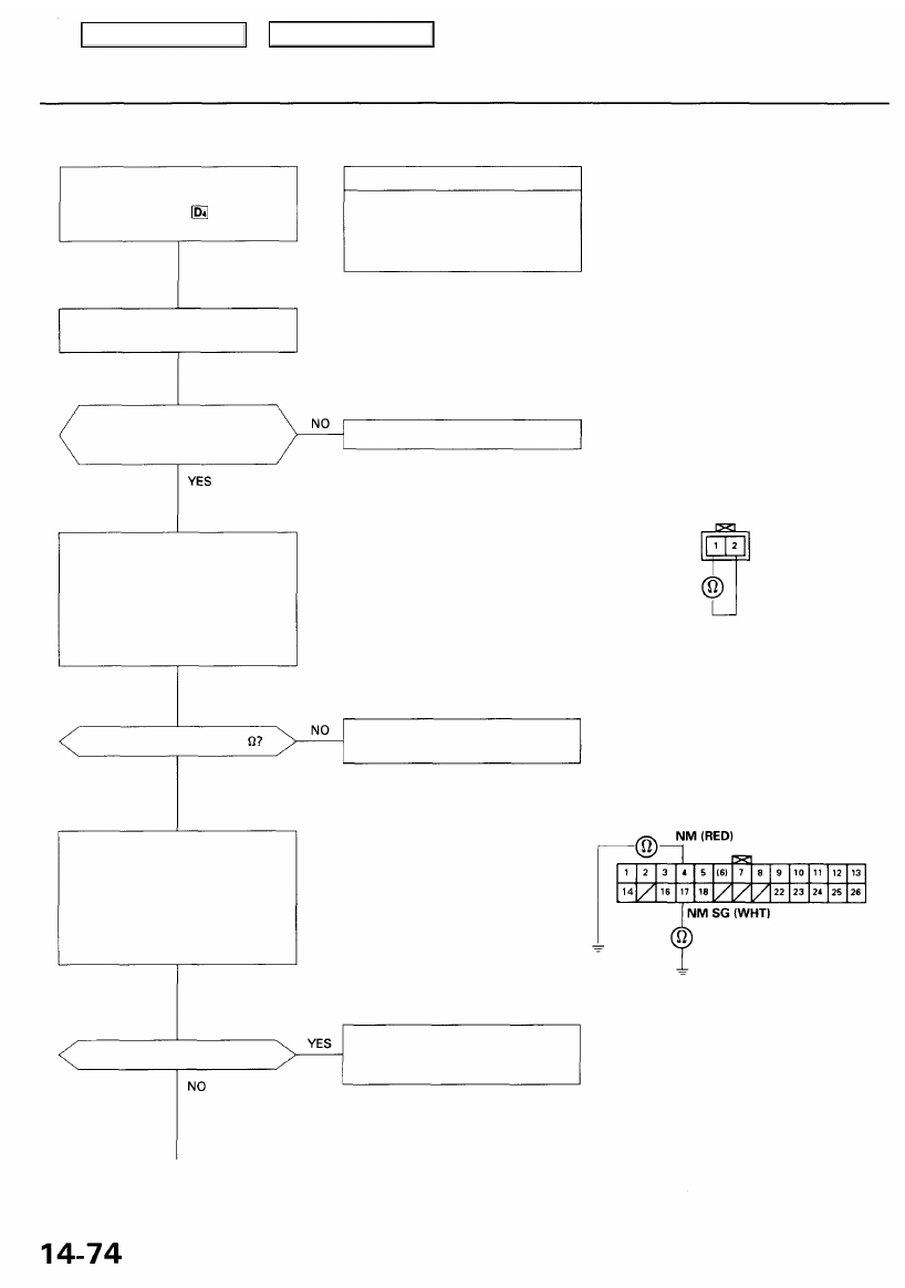
Troubleshooting Flowchart — Mainshaft Speed Sensor
• OBD II Scan Tool indicates Code
P0715.
• Self-diagnosis indicator
light indicates Code 15.
Check the mainshaft and counter-
shaft speed sensor installation.
Are the mainshaft and
countershaft speed sensors
installed properly?
Measure Mainshaft Speed Sensor
Resistance at the Sensor Con-
nector:
1. Disconnect the 2P connector
from the mainshaft speed
sensor.
2. Measure the resistance of the
mainshaft speed sensor.
Is the resistance 400 - 600
YES
Check Mainshaft Speed Sensor
for a Short Circuit:
1. Disconnect the E (26P) con-
nector from the PCM.
2. Check for continuity between
body ground and E4 terminal
and the E17 terminal individu-
ally.
Possible Cause
• Disconnected mainshaft speed
sensor connector
• Short or open in mainshaft
speed sensor wire
• Faulty mainshaft speed sensor
NOTE: Code P0715 (15) on the PCM
doesn't always mean there's an electrical
problem in the mainshaft or countershaft
speed sensor circuit; code P0715 (15)
may also indicate a mechanical problem
in the transmission.
Reinstall and recheck.
MAINSHAFT SPEED
SENSOR 2P CONNECTOR
Terminal side of male terminals
Replace the mainshaft speed sen-
sor.
Wire side of female terminals
Is there continuity?
Repair short in the wires between
the E4 and E17 terminals and the
mainshaft speed sensor.
PCM CONNECTOR E (26P)
Main Menu
Table of Contents
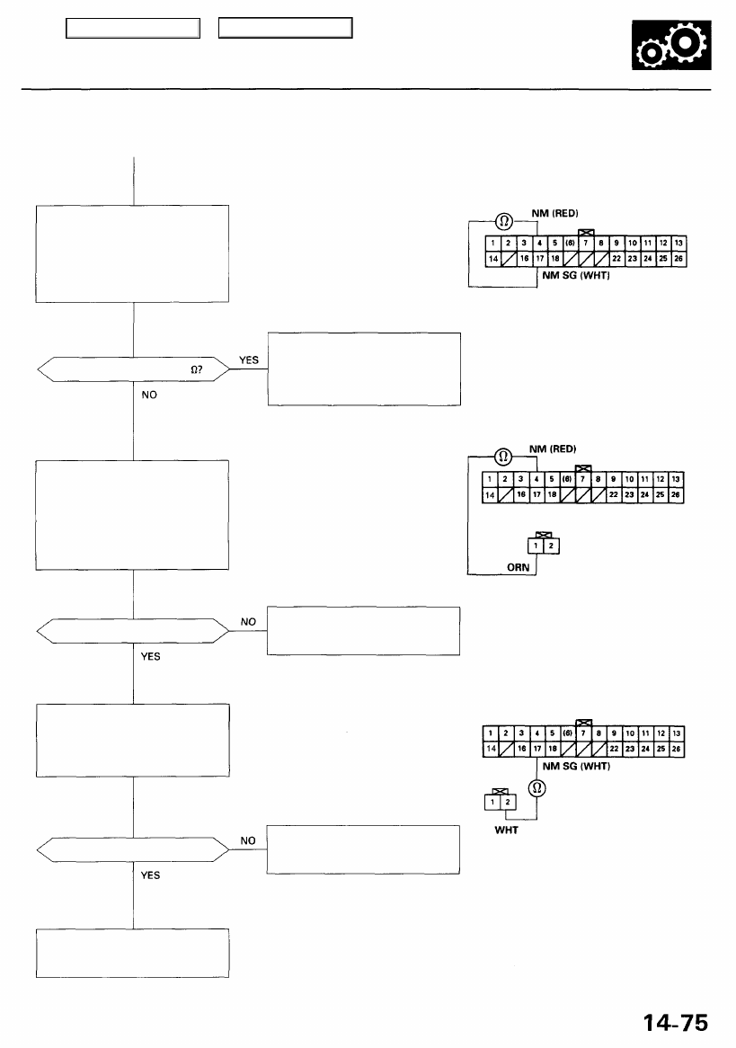
Measure Mainshaft Speed Sen-
sor Resistance:
1. Connect the mainshaft speed
sensor 2P connector.
2. Measure the resistance
between the E4 and E17 ter-
minals.
Is the resistance 400 - 600
Check NM Wire Continuity:
1. Disconnect the 2P connector
from the mainshaft speed
sensor.
2. Check for continuity between
the E4 terminal and the No. 1
terminal of the mainshaft
speed sensor connector.
Is there continuity?
Check NMSG Wire Continuity:
Check for continuity between the
E17 terminal and the No. 2 termi-
nal of the mainshaft speed sen-
sor connector.
Wire side of female terminals
Is there continuity?
Check for loose PCM connectors.
If necessary, substitute a known-
good PCM and recheck.
Run the Electrical Troubleshooting
Flowchart for code P0720 (code 9).
Check for loose PCM connectors. If
necessary, substitute a known-
good PCM and recheck.
MAINSHAFT SPEED
SENSOR 2P CONNECTOR
Wire side of female terminals
Repair open in the wire between
the E4 terminal and the main-
shaft speed sensor.
Repair open in the wire between
the E17 terminal and the main-
shaft speed sensor.
PCM CONNECTOR E (26P)
PCM CONNECTOR E (26P)
Main Menu
Table of Contents
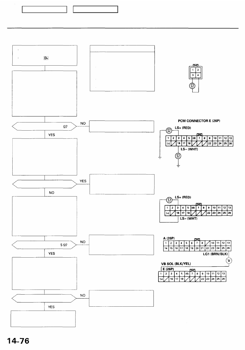
Electrical Troubleshooting
Troubleshooting Flowchart — A/T Clutch Pressure Control Solenoid Valve
• OBD II Scan Tool indicates Code
P1768.
• Self-diagnosis indicator light
indicates Code 16.
Measure A/T clutch pressure con-
trol solenoid valve Resistance at
Solenoid Connector:
1. Disconnect the shift solenoid
valve/A/T clutch pressure con-
trol solenoid valve harness 4P
connector.
2. Measure the resistance of the
A/T clutch pressure control
solenoid valve.
Is the resistance approx. 5
Check A/T Clutch Pressure
Control Solenoid Valve for a
Short Circuit:
1. Disconnect the E (26P) con-
nector from the PCM.
2. Check for continuity between
body ground and the E16 termi-
nal and E3 terminal individually.
Is there continuity?
Is the resistance approx.
Check the VB SOL Voltage:
1. Disconnect the A (26P) and E
(26P) connectors from the
PCM.
2. Turn the ignition switch ON (II).
3. Measure the voltage between
the E1 and A26 terminals.
Is there voltage?
Check for loose PCM connectors.
If necessary, substitute a known-
good PCM and recheck.
Possible Cause
• Disconnected A/T clutch pres-
sure control solenoid valve con-
nector
• Short or open in A/T clutch
pressure control solenoid valve
wire
• Faulty A/T clutch pressure con-
trol solenoid valve
• Open VB SOL line
Replace the A/T clutch pressure
control solenoid valve.
Repair short in the wires
between the E16 and E3 termi-
nals and the A/T clutch pressure
control solenoid valve.
Repair loose terminal or open in
the wires between the E16 and E3
terminals and the A/T clutch pres-
sure control solenoid valve.
Check for open in the wire
between the E1 terminal and the
under-hood fuse/relay box.
SHIFT SOLENOID
VALVE/A/T CLUTCH PRESSURE
CONTROL SOLENOID VALVE
HARNESS 4P CONNECTOR
Terminal side of male terminals
Wire side of female terminals
Measure A/T Clutch Pressure
Control Solenoid Valve Resistance:
1. Connect the shift solenoid
valve/A/T clutch pressure con-
trol solenoid valve harness 4P
connector.
2. Measure the resistance
between the E16 and E3 ter-
minals.
Main Menu
Table of Contents
Нет комментариевНе стесняйтесь поделиться с нами вашим ценным мнением.
Текст