Acura RL (1996-2004 year). Manual — part 429
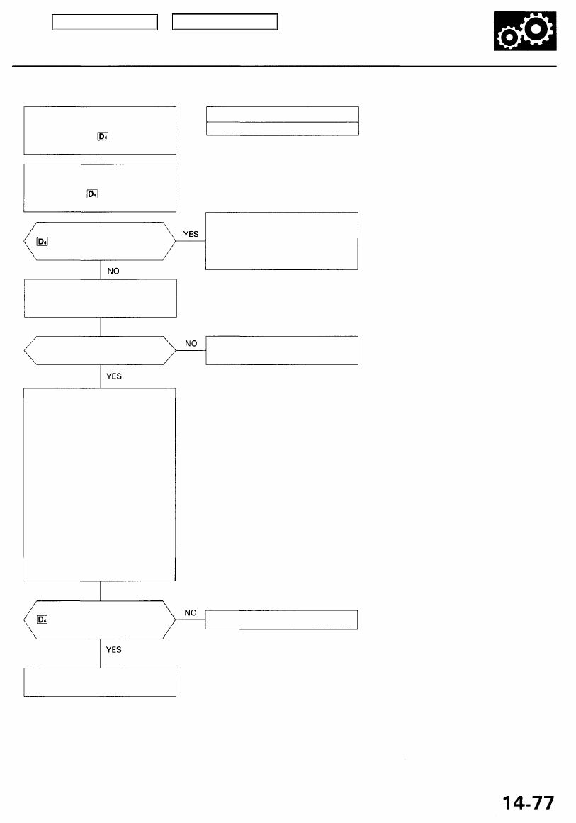
Troubleshooting Flowchart — Lock-up Control System
• OBD II Scan Tool indicates Code
P0740.
• Self-diagnosis indicator light
indicates Code 40.
Check for Another Code
Check whether the OBD II scan
tool or the indicator light
indicates another code.
Test Line Pressure:
Measure the line pressure (see
page
and
).
Is the line pressure within the
service limit?
Replace the Torque Converter
Clutch (Lock-up Control) Solenoid
Valves A and B and Recheck:
1. Replace the torque converter
clutch solenoid valves A and
).
2. Turn the ignition switch OFF
and reset the PCM by remov-
ing the BACK UP, RADIO fuse
in the under-hood fuse/relay
box for more than 10 seconds.
3. Using the OBD II scan tool,
check that the engine coolant
temperature is 176°F (80°C)
and above.
4. Drive the vehicle at 55 mph
(88 km/h) constantly for more
than one minute.
5. Recheck for code P0740 (40).
Does the OBD II scan tool or the
indicator light indicate another
code?
Possible Cause
Faulty Lock-up control system
Perform the Troubleshooting
Flowchart for the indicated
Code(s).
Recheck for code P0740 (40) after
troubleshooting.
NOTE: Do not continue with this trou-
bleshooting until the causes of any
other DTCs have been corrected.
Repair the hydraulic system as
necessary (see page
).
The system is OK at this time.
Does the OBD II scan tool or the
indicator light indicate another
code?
Replace the transmission and
torque converter.
Main Menu
Table of Contents
Electrical Troubleshooting
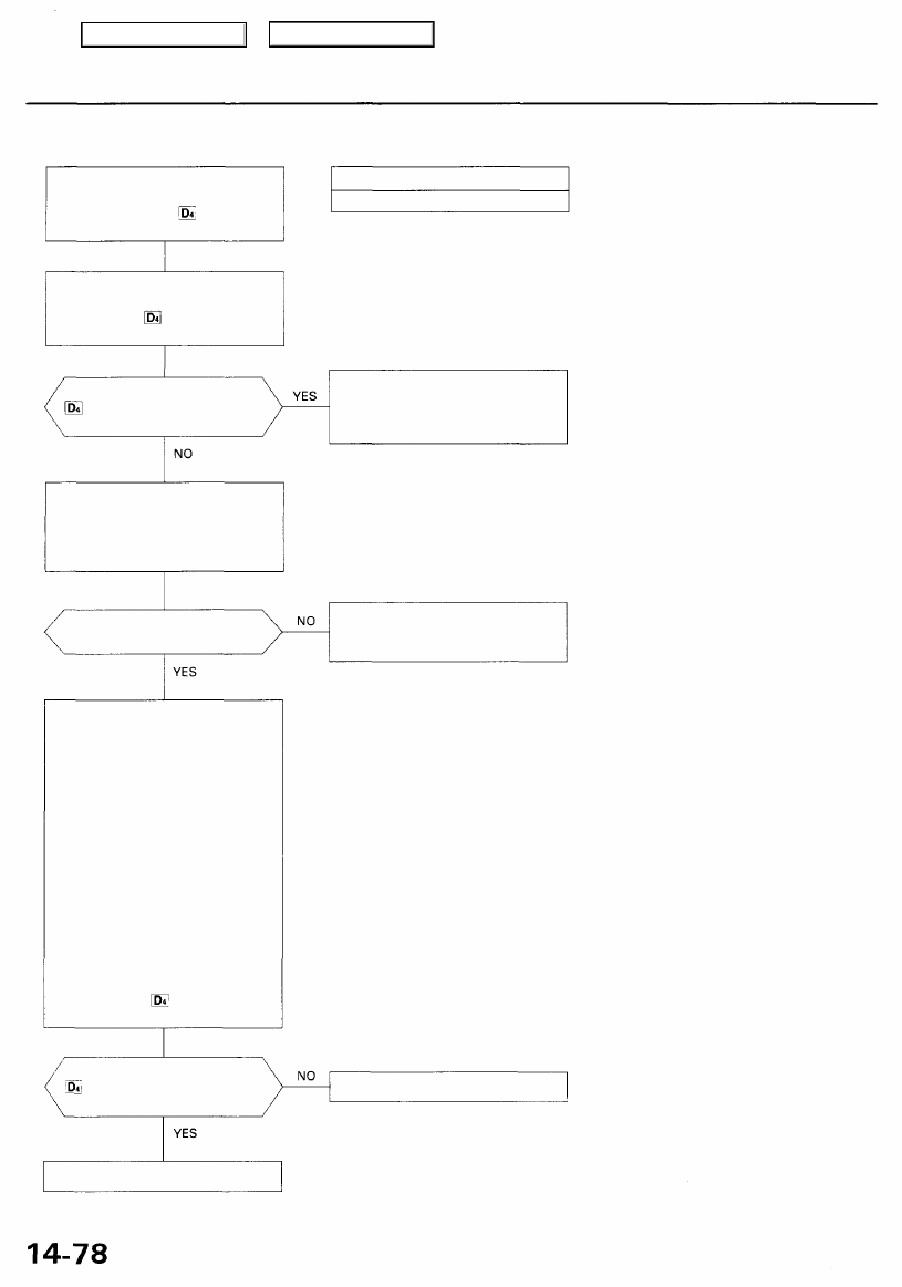
Troubleshooting Flowchart — Shift Control System
• OBD II Scan Tool indicates Code
P0730.
• Self-diagnosis indicator
light indicates Code 41.
Check for Another Code:
Check whether the OBD II scan
tool or the indicator light
indicates another code.
Does the OBD II scan tool or the
indicator light indicate another
code?
Test 1st, 2nd, 3rd, and 4th Clutch
Pressure:
Measure the 1st, 2nd, 3rd, and
4th clutch pressure (see page
thru
).
Is each clutch pressure within
the service limit?
Replace the Shift Solenoid Valves
A and B and the A/T Clutch
Pressure Control Solenoid Valve,
then Recheck:
1. Replace the shift solenoid
valves A and B (see page
).
2. Replace the A/T clutch pres-
sure control solenoid valve
(see page
).
3. Turn the ignition switch OFF
and reset the PCM memory
by removing the BACK UP,
RADIO fuse in the under-hood
fuse/relay box for more than
10 seconds.
4. Drive the vehicle at over 12
mph (20 km/h) in 1st, 2nd, 3rd
and 4th gear for more than 30
seconds in position.
5. Recheck for code P0730 (41).
Does the OBD II scan tool or the
indicator light indicate code
P0730 (41)?
Possible Cause
Faulty shift control system
Perform the Troubleshooting
Flowchart for the indicated
Code(s). Recheck for code P0730
(41) after troubleshooting.
NOTE: Do not continue with this trou-
bleshooting until the causes of any
other DTCs have been corrected.
Repair the hydraulic system as
necessary (see page
and
).
The system is OK at this time.
Replace the transmission.
Main Menu
Table of Contents
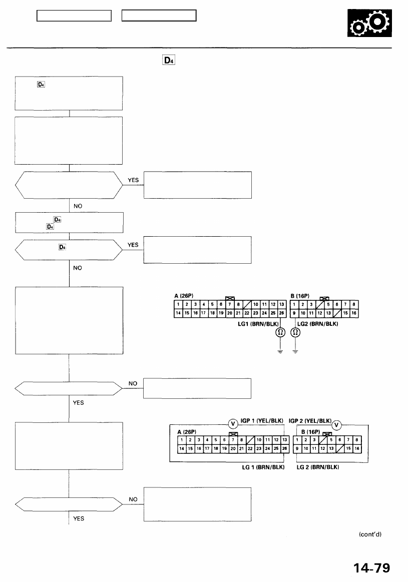
Troubleshooting Flowchart — Indicator Light Does Not Come On
Is the special tool (SCS Service
Connector) connected to the
service check connector?
Check the Indicator Light:
Shift to position.
Does the indicator light
come on?
Check the Ground Circuit:
1. Turn the ignition switch OFF.
2. Disconnect the A (26P) and B
(16P) connectors from the
PCM.
3. Check for continuity between
the A26 terminal and body
ground and the B9 terminal
and body ground.
Is there continuity?
Measure Power Supply Circuit
Voltage:
1. Turn the ignition switch ON (II).
2. Measure the voltage between
terminals A13 and A26 and
between terminals B1 and B9.
Is there battery voltage?
Disconnect the special tool from
the service check connector and
recheck.
Check for loose PCM connectors.
If necessary, substitute a known-
good PCM and recheck.
PCM CONNECTORS
Wire side of female terminals
Repair open in the wires between
the A26 or B9 terminals and G101.
Repair open or short in the wire
between the A13 and/or B1 termi-
nals, the PGM-FI main relay, and
the fuse box.
The indicator light does not
come on when the ignition switch
is first turned ON (II). (It should
come on for about 2 seconds.)
Check the Service Check Con-
nector:
Make sure the special tool (SCS
Service Connector) is not con-
nected to the service check con-
nector.
Main Menu
Table of Contents
Electrical Troubleshooting
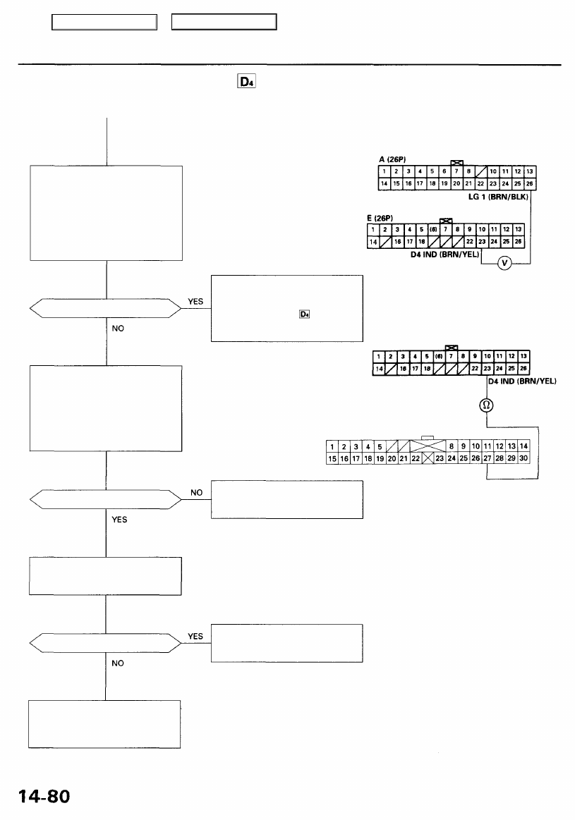
Troubleshooting Flowchart — Indicator Light Does Not Come On (cont'd)
Measure D4 IND Voltage:
1. Turn the ignition switch OFF.
2. Connect the A (26P) and
B (16P) connectors to the PCM.
3. Connect a digital multimeter
to the E23 and A26 terminals.
4. Turn the ignition switch ON (II)
and make sure that the voltage
is available for 2 seconds.
Is there voltage?
Check D4 IND for a Open Circuit:
1. Turn the ignition switch OFF.
2. Disconnect the E (26P) con-
nector from the PCM.
3. Check for continuity between
the E23 terminal and the B27
terminal of the gauge assembly
B (30P) connector.
Is there continuity?
Check D4 IND for a Short Circuit:
Check for continuity between the
E23 terminal and body ground.
Is there continuity?
PCM CONNECTORS
Check for open in the wire
between the E23 terminal and the
gauge assembly. If wire is OK,
check for a faulty indicator
light bulb or a faulty gauge assem-
bly printed circuit board.
Wire side of female terminals
PCM CONNECTOR E (26P)
GAUGE ASSEMBLY CONNECTOR B (30P)
Repair short in the wire between
the E23 terminal and the gauge
assembly.
Check for loose PCM connectors.
Check the transmission range
switch. If necessary, substitute a
known-good PCM and recheck.
Wire side of female terminals
Repair open in the wire between
the E23 terminal and the gauge
assembly.
Main Menu
Table of Contents
Нет комментариевНе стесняйтесь поделиться с нами вашим ценным мнением.
Текст