Acura RL (1996-2004 year). Manual — part 434
Interlock System
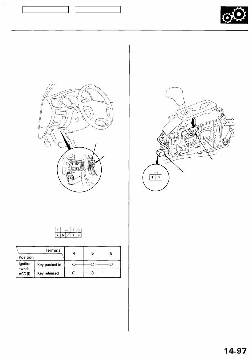
Key Interlock Solenoid Test
1. Remove the dashboard lower cover and knee bol-
).
2. Disconnect the 8P connector from the main wire
harness.
CONNECTOR
HOLDER
3. Check for continuity between the terminals in each
key position according to the table.
Wire side of female terminals
4. Check that the key cannot be removed with power and
ground connected to the No. 4 and No. 8 terminals.
• If the key cannot be removed, the key interlock sole-
noid is OK.
• If the key can be removed, replace the steering
lock assembly (the interlock solenoid is not avail-
able separately).
Shift Lock Solenoid Test
1. Remove the center console (see
).
2. Disconnect the shift lock solenoid 2P connector.
RELEASE LEVER
SHIR LOCK SOLENOID
2P CONNECTOR
Wire side of
female terminals
3. Connect battery power to the No. 1 terminal (+) and
to the No. 2 terminal (-) of the solenoid momentarily.
NOTE:
• Do not connect power to the No. 2 (-) terminal
(reverse polarity) or you will damage the diode
inside the solenoid.
• Make sure there is clearance between the stop
pin and base bracket when the solenoid is ON
and OFF.
4. Check that the shift lock releases when the release
lever is pushed, and that it locks when the lever is
released.
5. If the solenoid does not work, replace it.
IGNITION SWITCH 8P CONNECTOR
8P
CONNECTOR
Main Menu
Table of Contents
Interlock System
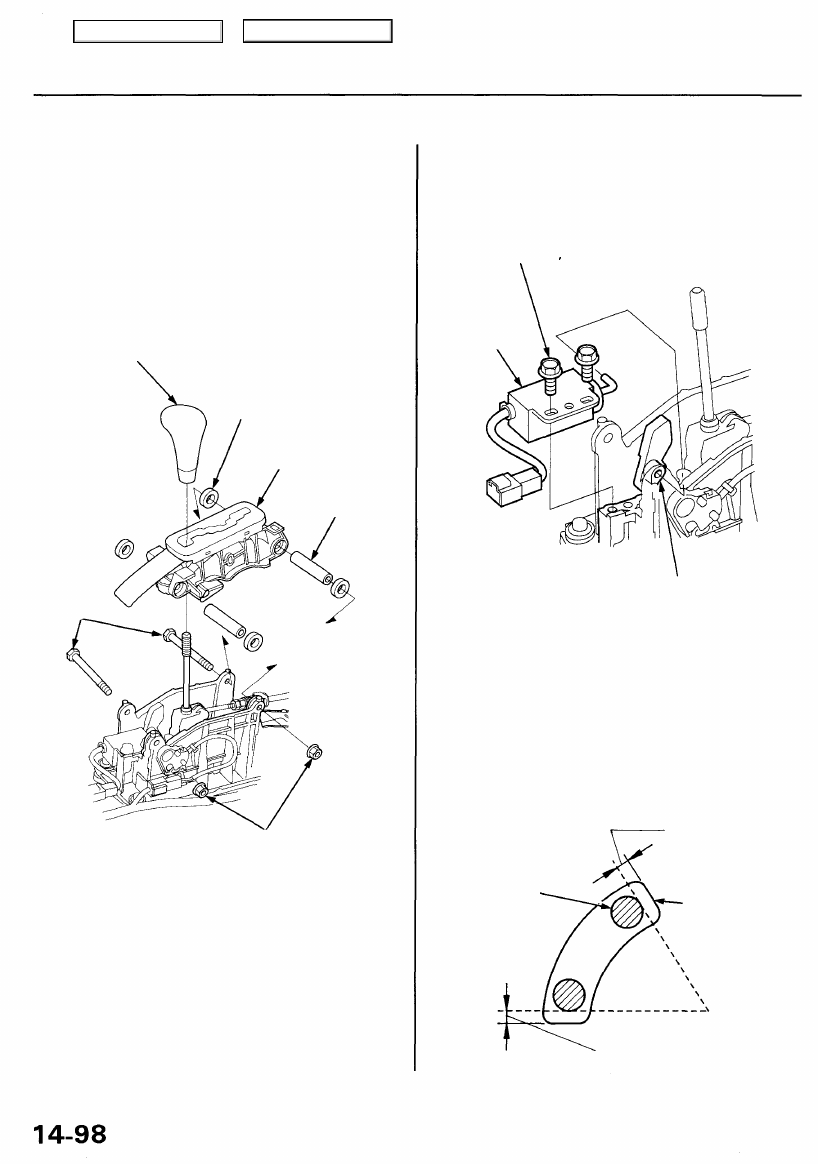
Shift Lock Solenoid Replacement
1. Remove the center console and shift lever knob (see
).
2. Disconnect the connectors from the shift lock sole-
noid and park pin switch.
3. Remove the two locknuts and through bolts, then
remove the A/T gear position panel.
SHIFT LEVER
KNOB
RUBBER GROMMET
A/T GEAR POSITION
PANEL
COLLAR
THROUGH
BOLTS
LOCKNUTS
6 x 1.0 mm
8 N-m (0.8 kgf-m,
6 Ibf-ft)
4. Remove the two mounting bolts, then remove the
shift lock solenoid.
6 x 1.0 mm
8 N-m (0.8 kgf-m
6 Ibf-ft)
SHIFT LOCK
SOLENOID
SHIFT LOCK
STOP
5. Install the shift lock solenoid in the reverse order of
removal.
NOTE: Make sure there is clearance between the
stop pin and base bracket when the solenoid is ON
and OFF.
SOLENOID
ON
STOP PIN
SOLENOID
OFF
CLEARANCE
BASE BRACKET
CLEARANCE
Main Menu
Table of Contents
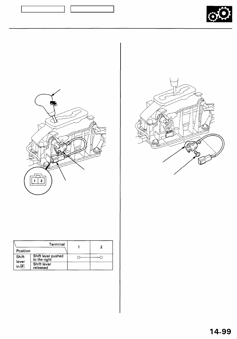
Park Pin Switch Test/Replacement
1. Remove the center console (see
).
2. Disconnect the park pin switch 2P connector.
SHIFT LEVER
Push the shift lever to the right
in the direction shown.
PARK PIN
SWITCH
PARK PIN
SWITCH 2P
CONNECTOR
Terminal side of
male terminals
3. Check for continuity between the terminals in each
switch lever position according to the table.
4. If necessary, replace the park pin switch.
5. Remove the screw, then remove the park pin switch
from the base bracket.
PARK PIN
SWITCH
SCREW
5 x 0.8 mm
4 N-m (0.4 kgf-m, 3 Ibf-ft)
Main Menu
Table of Contents
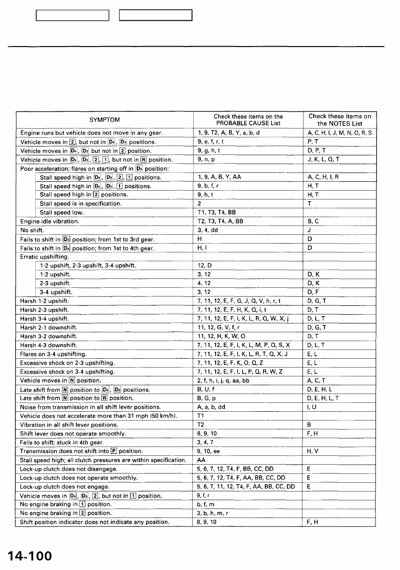
Symptom-to-Component Chart
Hydraulic System
Before troubleshooting a problem in the hydraulic system, check the self-diagnosis indicator light indication. If the light
indicates a trouble code, perform the electrical troubleshooting according to the Electrical System Symptom-to-
Component Chart. If the indicator light does not indicate a trouble code and a failure is not found during electrical trou-
bleshooting, perform hydraulic troubleshooting using the chart.
Main Menu
Table of Contents
Нет комментариевНе стесняйтесь поделиться с нами вашим ценным мнением.
Текст