Acura RL (1996-2004 year). Manual — part 433
Replacement
Make sure lifts, jacks and safety stands are placed properly (see
).
1. Raise the front of the vehicle, and support it with safety stands (see
).
2. Set the parking brake, and block both rear wheels securely.
3. Shift the transmission to the position.
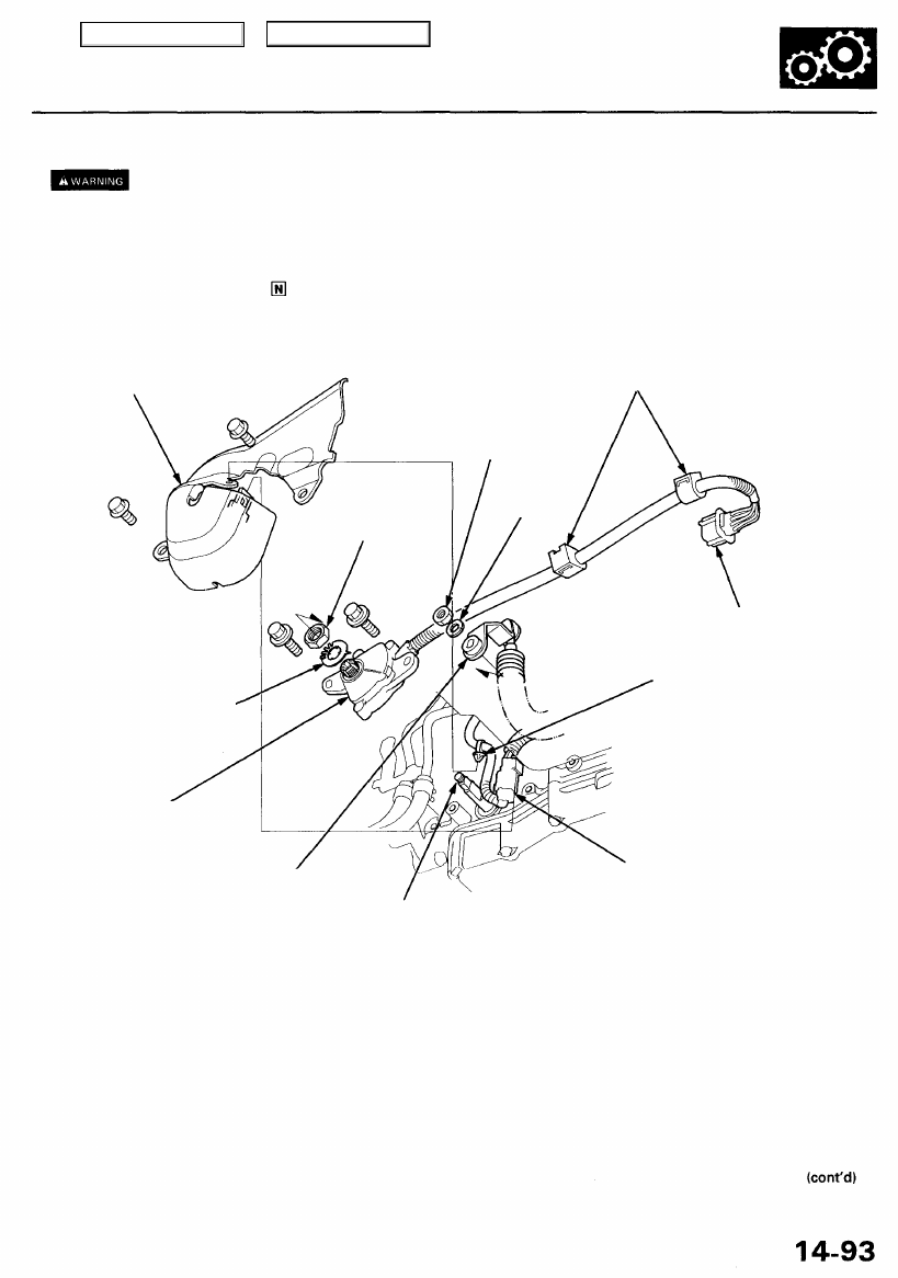
4. Remove the clamp, then disconnect the transmission range switch connector.
SHIFT CABLE
COVER
CLAMPS
TRANSMISSION RANGE
SWITCH CONNECTOR
SHIFT SOLENOID VALVE/
A/T CLUTCH PRESSURE
CONTROL SOLENOID VALVE
HARNESS CLAMP
TRANSMISSION RANGE
SWITCH
SHIFT SOLENOID VALVE/
A/T CLUTCH PRESSURE
CONTROL SOLENOID VALVE
HARNESS CONNECTOR
5. Remove the clamp from the transmission range switch harness bracket on the rear cover.
6. Remove the shift cable cover mounting bolts.
7. Remove the shift solenoid valve/A/T clutch pressure control solenoid valve harness clamp and connector from the
shift cable cover.
8. Disconnect the shift solenoid valve/A/T clutch pressure control solenoid valve harness connector, then remove the
shift cable cover from the transmission.
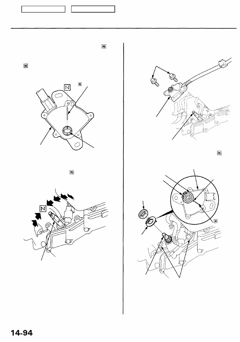
9. Remove the control lever.
10. Remove the locknut and lock washer.
11. Remove the transmission range switch.
LOCKNUT
LOCK WASHER
Replace.
CONTROL SHAFT
CONTROL LEVER
SPRING
WASHER
LOCKNUT
Main Menu
Table of Contents
Transmission Range Switch (A/T Gear Position Switch)
Replacement (cont'd)
12. Set a new transmission range switch to the posi-
tion as shown.
NOTE: The transmission range switch clicks in the
position.
POSITION MARK
TRANSMISSION RANGE
SWITCH
CONTROL SHAFT
HOLE
13. Set the control shaft to the position.
CONTROL SHAFT
14. Install the transmission range switch on the control
shaft, and loosely install the bolts.
6 x 1.0 mm BOLTS
Loosely install.
TRANSMISSION RANGE
SWITCH
CONTROL SHAFT
15. Install a new lock washer on the transmission range
switch by aligning its projected tip with the posi-
tion mark on the transmission range switch as shown.
LOCK WASHER
LOCK TABS
LOCKNUT
12 N-m (1.2 kgf-m,
8.7 Ibf-ft)
TRANSMISSION RANGE
SWITCH
PROJECTED
TIP
POSITION
MARK
LOCK WASHER
Replace.
CONTROL
SHAFT
6 x 1.0 mm
12 N-m (1.2 kgf-m,
8.7 Ibf-ft)
16. Tighten the locknut while holding the control shaft,
then bend the lock tabs against the locknut.
17. Tighten the 6 mm bolts to the specified torque.
Main Menu
Table of Contents
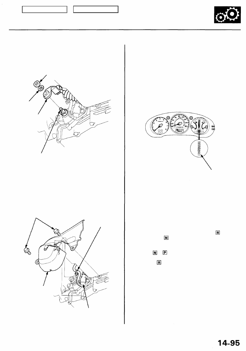
18. Install the control lever.
CAUTION: Take care not to bend the shift cable.
SPRING
WASHER
CONTROL SHAFT
19. Connect the shift solenoid valve/A/T clutch pressure
control solenoid valve harness connector.
20. Install the shift solenoid valve/A/T clutch pressure
control solenoid valve harness clamp to the shift
cable cover, then install the shift cable cover onto
the transmission.
CLAMP
SHIFT CABLE
COVER
SHIFT SOLENOID VALVE/
A/T CLUTCH PRESSURE
CONTROL SOLENOID VALVE
HARNESS CONNECTOR
21. Connect the transmission range switch harness
connector, then clamp the harness clamp on the
brackets.
22. Turn the ignition switch ON (II). Move the shift lever
through all gears, and check the transmission range
switch synchronization with the A/T gear position
indicator.
GAUGE ASSEMBLY
A/T GEAR POSITION
INDICATOR
23. If the transmission range switch is not synchronized
with the A/T gear position indicator, loosen the bolts
securing the transmission range switch and adjust
the transmission range switch installation.
24. Start the engine. Move the shift lever through all
gears, and verify the following:
• The shift lever cannot be moved to the position
from the position without pushing the shift
lever.
• The engine will not start in any drive gear, only in
the or position.
• The back-up lights come on when the shift lever is
in the position.
8 x 1.25 mm
16 N-m (1.6 kgf-m, 12 Ibf-ft)
CONTROL
LEVER
6 x 1.0 mm
12 N-m (1.2 kgf-m,
8.7 Ibf-ft)
Main Menu
Table of Contents
A/T Gear Position Indicator
Indicator Input Test
SRS components are located in this area. Review the SRS component locations, precautions, and procedures in the SRS
(
) before performing repairs or service.
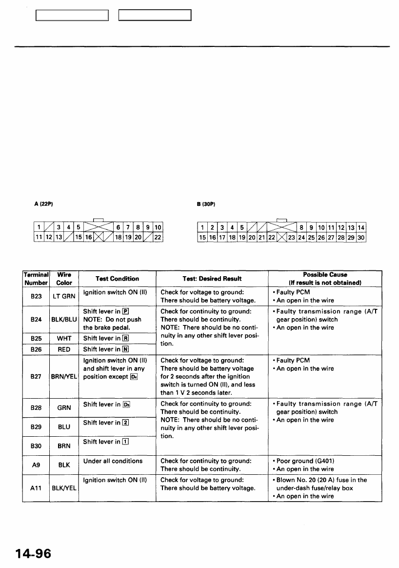
1. Remove the gauge assembly from the dashboard (see
), and disconnect the 30P and 22P connectors from
).
2. Inspect the connector and socket terminals to be sure they are all making good contact.
• If the terminals are bent, loose, or corroded, repair them as necessary, and recheck the system.
• If the terminals look OK, make the following input tests at the 30P and 22P connectors.
— If any test indicates a problem, find and correct the cause, then recheck the system.
— If all the input tests prove OK, but the indicator is faulty, replace the printed circuit board.
GAUGE ASSEMBLY CONNECTORS
Wire side of female terminals
Main Menu
Table of Contents
Нет комментариевНе стесняйтесь поделиться с нами вашим ценным мнением.
Текст