Acura RL (1996-2004 year). Manual — part 432
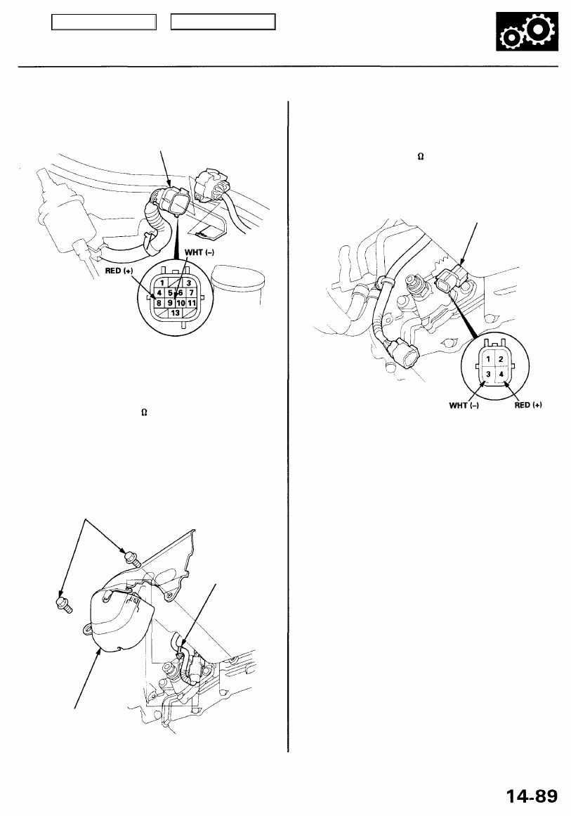
A/T Clutch Pressure Control Solenoid Valve
Test
1. Disconnect the transmission sub-harness connector
(HP).
2. Measure the resistance between the No. 8 and No. 9
terminals of the transmission sub-harness connector.
STANDARD: 4.0 - 6.0 (at 70°F, 20°C)
3. If the resistance is out of specification, remove the
shift cable cover, and disconnect the shift solenoid
valve/A/T clutch pressure control solenoid valve
harness connector.
CLAMP
SHIFT CABLE
COVER
4. Measure the resistance between the No. 3 and No. 4
terminals of the shift solenoid valve/A/T clutch pres-
sure control solenoid valve harness connector.
STANDARD: 4.0 - 6.0 (at 70°F, 20°C)
SHIFT SOLENOID VALVE/
A/T CLUTCH PRESSURE
CONTROL SOLENOID VALVE
HARNESS CONNECTOR
Terminals side of
male terminals
• If the resistance is within specification, replace
the transmission sub-harness.
• If the resistance is out of specification, replace
the A/T clutch pressure control solenoid valve.
5. If the resistance is within the standard, connect the
No. 4 terminal of the shift solenoid valve/A/T clutch
pressure control solenoid harness connector to the
battery positive terminal, and connect the No. 3 ter-
minal to the battery negative terminal. A clicking
sound should be heard. If no clicking sound is heard,
replace the A/T clutch pressure control solenoid
valve.
NOTE: If A/T clutch pressure control solenoid valve
replacement is required, see these headings:
• Lower Valve Body
Removal/Installation . . . . . . . . ...
Disassembly/Reassembly . . . . . . ..
• Throttle Valve Body/A/T Clutch Pressure Control
Solenoid Valve
Replacement . . . . . . . . . . . ...
6 x 1.0 mm
12 N-m (1.2 kgf-m,
8.7 Ibf-ft)
TRANSMISSION SUB-HARNESS
CONNECTOR (14P)
Terminal side of
male terminals
Main Menu
Table of Contents
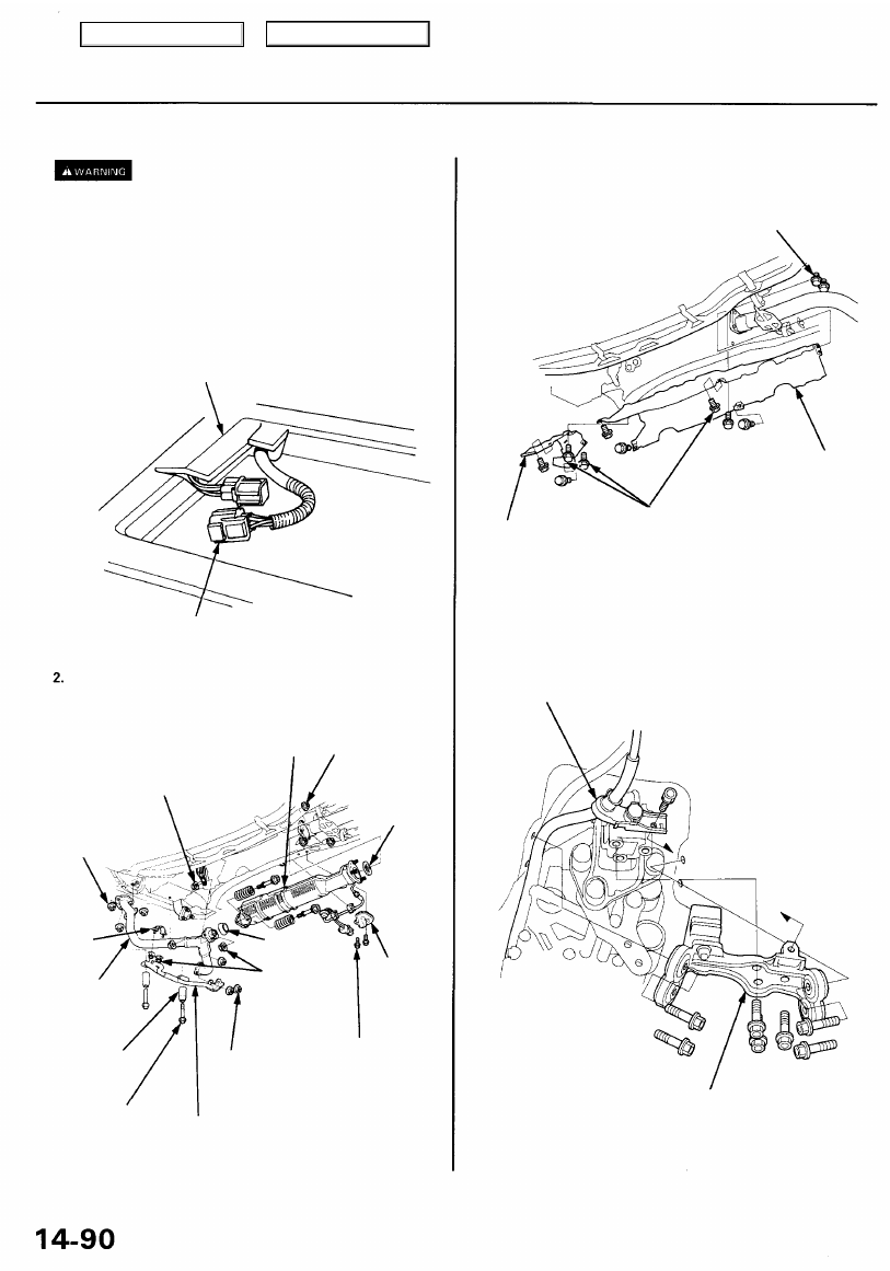
Mainshaft/Countershaft Speed Sensors
Replacement
Make sure lifts, jacks, and safety stands
).
1. Pull the carpet back to expose the secondary heated
oxygen sensor (secondary HO2S) connector. Discon-
nect the connector, then push it out under the vehi-
cle.
NOTE: The secondary HO2S connector is under the
passenger's seat.
SECONDARY HO2S CONNECTOR
Remove the exhaust pipe A bracket, then remove
exhaust pipe A.
BAND
EXHAUST
PIPE A
TRANSMISSION
STOP COLLAR
THREE WAY
CATALYTIC
CONVERTER
SECONDARY
HO2S
HARNESS
COVER
6 x 1.0 mm
9.8 N-m (1.0 kgf-m,
7.2 Ibf-ft)
3. Remove the secondary HO2S harness cover, then
remove the three way catalytic converter.
4. Remove the heat shields.
6 x 1.0 mm
9.8 N-m (1.0 kgf-m,
7.2 Ibf-ft)
HEAT
SHIELD
HEAT
SHIELD
6 x 1.0 mm
9.8 N-m (1.0 kgf-m,
7.2 Ibf-ft)
5. Place a jack under the transmission, and raise the
transmission just enough to take weight off of the
mounts, then remove the bolt securing the shift
cable guide bracket and the transmission beam.
SHIFT CABLE
GUIDE BRACKET
TRANSMISSION BEAM
CARPET
10 x 1.25 mm
33 N-m (3.4 kgf-m,
25 Ibf-ft)
Replace.
GASKET
Replace.
8 x 1.25 mm
22 N-m (2.2 kgf-m,
16 Ibf-ft)
Replace.
10 x 1.25 mm
54 N-m (5.5 kgf-m,
40 Ibf-ft)
Replace.
GASKET
Replace.
8 x 1.25 mm
22 N-m (2.2 kgf-m,
16 Ibf-ft)
Replace.
10 x 1.25 mm
38 N-m
(3.9 kgf-m, 28 Ibf-ft)
EXHAUST
PIPE A BRACKET
10 x 1.25 mm
33 N-m (3.4 kgf-m,
25 Ibf-ft)
Replace.
Main Menu
Table of Contents
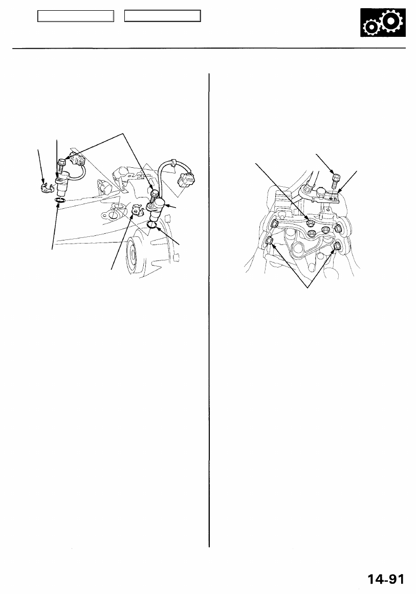
O-RING
Replace.
COUNTER-
SHAFT
SPEED
SENSOR
O-RING
Replace.
8. Replace the O-rings with new ones before reassem-
bling the mainshaft and countershaft speed sensors.
9. Install washers on the mainshaft and countershaft
speed sensors, then install the sensors on the trans-
mission housing.
10. Raise the transmission with a jack.
11. Install the transmission beam on the rear transmis-
sion mount bracket/mount, then tighten the four
bolts loosely.
TRANSMISSION BEAM
BOLTS
10 x 1.25 mm
38 N-m (3.9 kgf-m,
28 Ibf-ft)
6 x 1.0 mm
9.8 N-m (1.0 kgf-m,
7.2 Ibf-ft)
SHIFT CABLE
GUIDE BRACKET
TRANSMISSION BEAM BOLTS
10 x 1.25 mm
38 N-m (3.9 kgf-m, 28 Ibf-ft)
12. Tighten the four beam bolts to the specified torque,
then tighten the three inner bolts to the specified
torque.
13. Install the shift cable guide bracket on the transmis-
sion beam.
14. Install the heat shields.
15. Install exhaust pipe A and the three way catalytic
converter, then install the exhaust pipe A bracket.
16. Push the secondary HO2S connector into the vehi-
cle, then secure it with the harness grommet.
17. Install the secondary HO2S harness cover.
18. Connect the secondary HO2S connector.
6. Lower the transmission.
7. Remove the 6 mm bolt from the transmission hous-
ing, and remove the mainshaft and countershaft
speed sensors.
6 x 1.0 mm
12 N-m (1.2 kgf-m, 8.7 Ibf-ft)
MAINSHAFT
SPEED SENSOR
WASHER
WASHER
Main Menu
Table of Contents
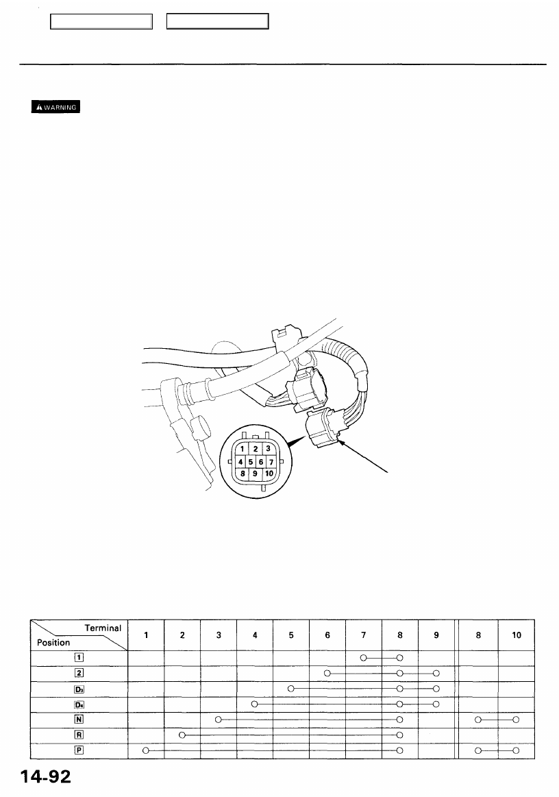
Transmission Range Switch (A/T Gear Position Switch)
Test
Make sure lifts, jacks, and safety stands are placed properly (see
).
1. Raise the front of the vehicle, and support it with safety stands (see
).
2. Set the parking brake, and block both rear wheels securely.
3. Pull the carpet back to expose the secondary heated oxygen sensor (secondary HO2S) connector. Disconnect the con-
nector, then push it out under the vehicle (see page
).
NOTE: The secondary HO2S connector is under the passenger's seat.
4. Remove the exhaust pipe A bracket, then remove exhaust pipe A.
5. Remove the secondary HO2S harness cover, then remove the three way catalytic converter.
6. Remove the heat shields.
7. Disconnect the transmission range switch connector.
TRANSMISSION RANGE
SWITCH CONNECTOR
(10P)
Terminal side of male terminals
8. Check for continuity between the terminal in each switch position according to the table below.
• Move the shift lever back and forth without pushing the shift lever at each switch position, and check for continuity
within the range of its free play.
• If there is no continuity within the range of free play, adjust the transmission range switch.
Neutral
Position Switch
Transmission Range Switch
Main Menu
Table of Contents
Нет комментариевНе стесняйтесь поделиться с нами вашим ценным мнением.
Текст