Acura RL (1996-2004 year). Manual — part 528
DTC 53: Motor Stuck ON
With the ignition switch ON
(II), the ABS indicator does
not go off.
With the SCS service connec-
tor connected (see page
), DTC 53 is indicated.
Check that the pump motor oper-
ates with the ignition switch OFF.
Does the pump motor operate?
Remove the ABS UNIT (7.5 A) fuse
in the under-hood fuse/relay box.
Is the fuse OK?
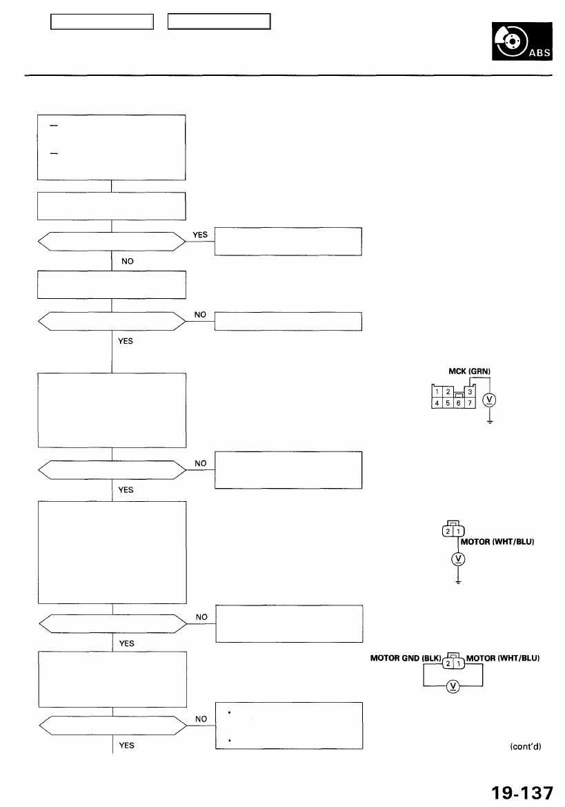
Check for an open in the MCK
circuit:
1. Turn the ignition switch ON (II).
2. Measure the voltage between
the under-hood fuse/relay box
7P connector terminal No. 3
and body ground.
Is there about 11 V?
Check for an open in the MOTOR
circuit:
1. Reinstall the ABS UNIT (7.5 A)
fuse in the under-hood fuse/
relay box.
2. Disconnect the pump motor
connector.
3. Measure the voltage between
terminal No. 1 and body
ground.
Is there about 11 V?
Check for an open in the MOTOR
GND circuit:
Measure the voltage between the
pump motor connector terminal
No. 1 and No. 2.
Is there about 11 V?
Replace the pump motor relay.
(Pump motor relay stuck ON.)
Replace the fuse and recheck.
UNDER-HOOD FUSE/RELAY BOX
7P CONNECTOR
Wire side of female terminals
Repair open in the wire between
the under-hood fuse/relay box
and the ABS control unit.
PUMP MOTOR CONNECTOR
Terminal side of female terminals
Repair open in the wire between
the under-hood fuse/relay box
and the pump motor.
Repair open in the wire between
the pump motor and body
ground.
Repair poor ground (G251).
Main Menu
Table of Contents
Troubleshooting
DTC 53: Motor Stuck ON (cont'd)
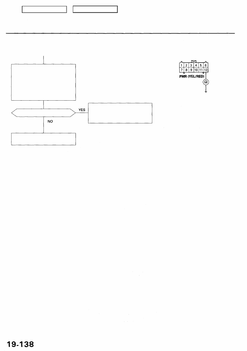
ABS CONTROL UNIT 12P CONNECTOR
Check for a short to body ground
in the PMR circuit:
1. Remove the pump motor relay.
2. Disconnect the ABS control
unit 12P connector.
3. Check for continuity between
terminal No. 12 and body
ground.
Wire side of female terminals
Is there continuity?
Repair short to body ground
between the under-hood fuse/
relay box and the ABS control
unit.
If the problem occurs again,
replace the ABS control unit.
Main Menu
Table of Contents
DTC 54: Fail-safe Relay
With the ignition switch ON
(II), the ABS indicator does
not go off.
With the SCS service connec-
tor connected (see page
), DTC 54 is indicated.
Check the ABS (20 A) fuse in the
under-hood fuse/relay box, and
reinstall the fuse if it is OK.
Is the fuse OK?
Replace the fuse and recheck.
NOTE: If the fuse is blown after the fail-
safe relay is on, check for a short to
body ground in the wire between the
fail-safe relay, pump motor relay and
modulator unit.
Wire colors of fail-safe relay connector:
BRN/BLK, WHT/GRN, BLK, YEL/GRN
Is the relay OK?
Replace the fail-safe relay.
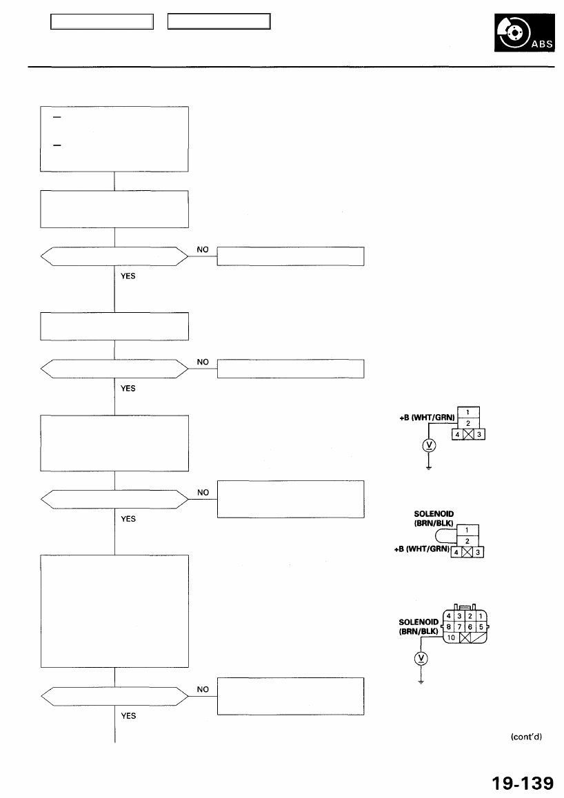
Check for an open in the +B cir-
cuit:
Measure the voltage between the
fail-safe relay connector terminal
No. 2 and body ground.
FAIL-SAFE RELAY CONNECTOR
Is there battery voltage?
Repair open in the wire between
the under-hood fuse/relay box
and the fail-safe relay.
Terminal side of female terminals
Check for an open in the solenoid
power source circuit:
1. Connect the fail-safe relay
connector terminal No. 1 to
No. 2 with a jumper wire.
2. Disconnect the modulator unit
connector.
3. Measure the voltage between
the modulator unit connector
terminal No. 10 and body
ground.
MODULATOR UNIT CONNECTOR
Is there battery voltage?
Repair open in the wire between
the fail-safe relay and the modu-
lator unit.
Terminal side of female terminals
JUMPER WIRE
Check the fail-safe relay (see
).
Main Menu
Table of Contents
Troubleshooting
DTC 54: Fail-safe Relay (cont'd)
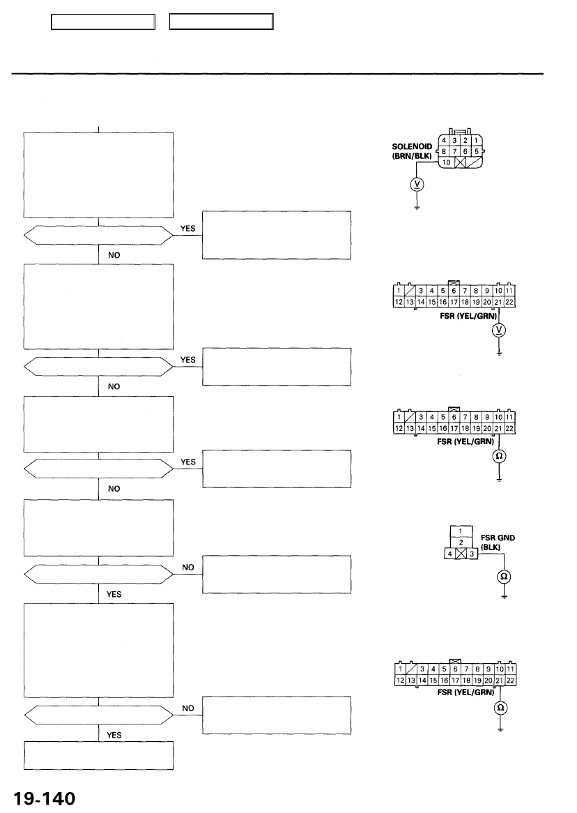
Check for a short to power in the
solenoid power source circuit:
1. Remove the jumper wire from
the fail-safe relay connector.
2. Measure the voltage between
the modulator unit connector
terminal No. 10 and body
ground.
Is there battery voltage?
Check for a short to power in the
FSR circuit:
1. Disconnect the ABS control
unit 22P connector.
2. Turn the ignition switch ON (II).
3. Measure the voltage between
the terminal No. 21 and body
ground.
Is there battery voltage?
Check for a short to body ground
in the FSR circuit:
Check for continuity between the
ABS control unit 22P connector
terminal No. 21 and body ground.
Is there continuity?
Check for an open in the FSR
GND circuit:
Check for continuity between the
fail-safe relay connector terminal
No. 3 and body ground.
Is there continuity?
Check for an open in the FSR cir-
cuit:
1. Connect the fail-safe relay
connector terminals No. 3 and
No. 4 with a jumper wire.
2. Check for continuity between
the ABS control unit 22P con-
nector terminal No. 21 and
body ground.
Is there continuity?
If the problem occurs again,
replace the ABS control unit.
Repair short to power in the wire
between the fail-safe relay, mod-
ulator unit and the under-hood
fuse/relay box.
Terminal side of female terminals
ABS CONTROL UNIT 22P CONNECTOR
Repair short to power in the wire
between the ABS control unit
and the fail-safe relay.
Wire side of female terminals
Repair short to body ground in
the wire between the ABS con-
trol unit and the fail-safe relay.
FAIL-SAFE RELAY CONNECTOR
Repair open in the wire between
the fail-safe relay and body
ground.
Terminal side of female terminals
ABS CONTROL UNIT 22P CONNECTOR
Repair open in the wire between
the ABS control unit and the fail-
safe relay.
Wire side of female terminals
MODULATOR UNIT CONNECTOR
Main Menu
Table of Contents
Нет комментариевНе стесняйтесь поделиться с нами вашим ценным мнением.
Текст