Acura RL (1996-2004 year). Manual — part 526
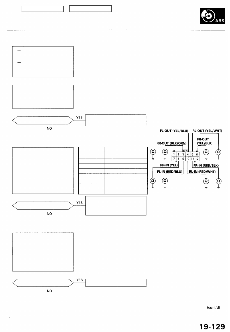
DTC 31, 32, 33, 34, 35, 36, 37, 38: Solenoid
With the ignition switch ON
(II), the ABS indicator does
not go off.
With the SCS service connec-
tor connected (see page
), DTCs 31 - 38 are indi-
cated.
Problem verification:
1. Turn the ignition switch OFF,
then turn the ignition switch
ON (II) again.
2. Verify the DTC.
Is DTC 54 indicated?
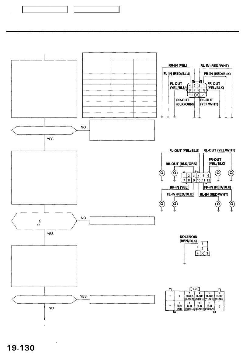
Check for a short to body ground
in the solenoid:
1. Connect the modulator unit
connector.
2. Check for continuity between
the appropriate ABS control
unit 12P connector solenoid
circuit terminal and body
ground (see table).
Is there continuity?
Perform the appropriate trou-
bleshooting for DTC 54.
ABS CONTROL UNIT 12P CONNECTOR
DTC
31: FR-IN
32: FR-OUT
33: FL-IN
34: FL-OUT
35: RR-IN
36: RR-OUT
37: RL-IN
38: RL-OUT
Appropriate Terminal
No. 11
No. 6
No. 9
No. 4
No. 8
No. 3
No. 10
No. 5
Wire side of female terminals
Repair short to body ground in
the appropriate solenoid circuit
wire between the ABS control
unit and the modulator unit.
Replace the modulator unit.
Check for a short to body ground
in the solenoid circuit:
1. Turn the ignition switch OFF.
2. Disconnect the modulator
unit connector and the ABS
control unit 12P connector.
3. Check for continuity between
the appropriate ABS control
unit 12P connector solenoid
circuit terminal and body
ground (see table).
Is there continuity?
Main Menu
Table of Contents
Troubleshooting
DTC 31, 32, 33, 34, 35, 36, 37, 38: Solenoid (cont'd)
Check for an open in the solenoid
circuit:
1. Disconnect the modulator
unit connector.
2. Connect the appropriate sole-
noid circuit terminal to body
ground with a jumper wire
(see table).
3. Check for continuity between
the appropriate ABS control
unit 12P connector solenoid
circuit terminal and body
ground (see table).
Is there continuity?
Is the resistance OK?
IN: 8-10 (at 20°C, 68°F)
OUT: 3 - 5 (at 20°C, 68°F)
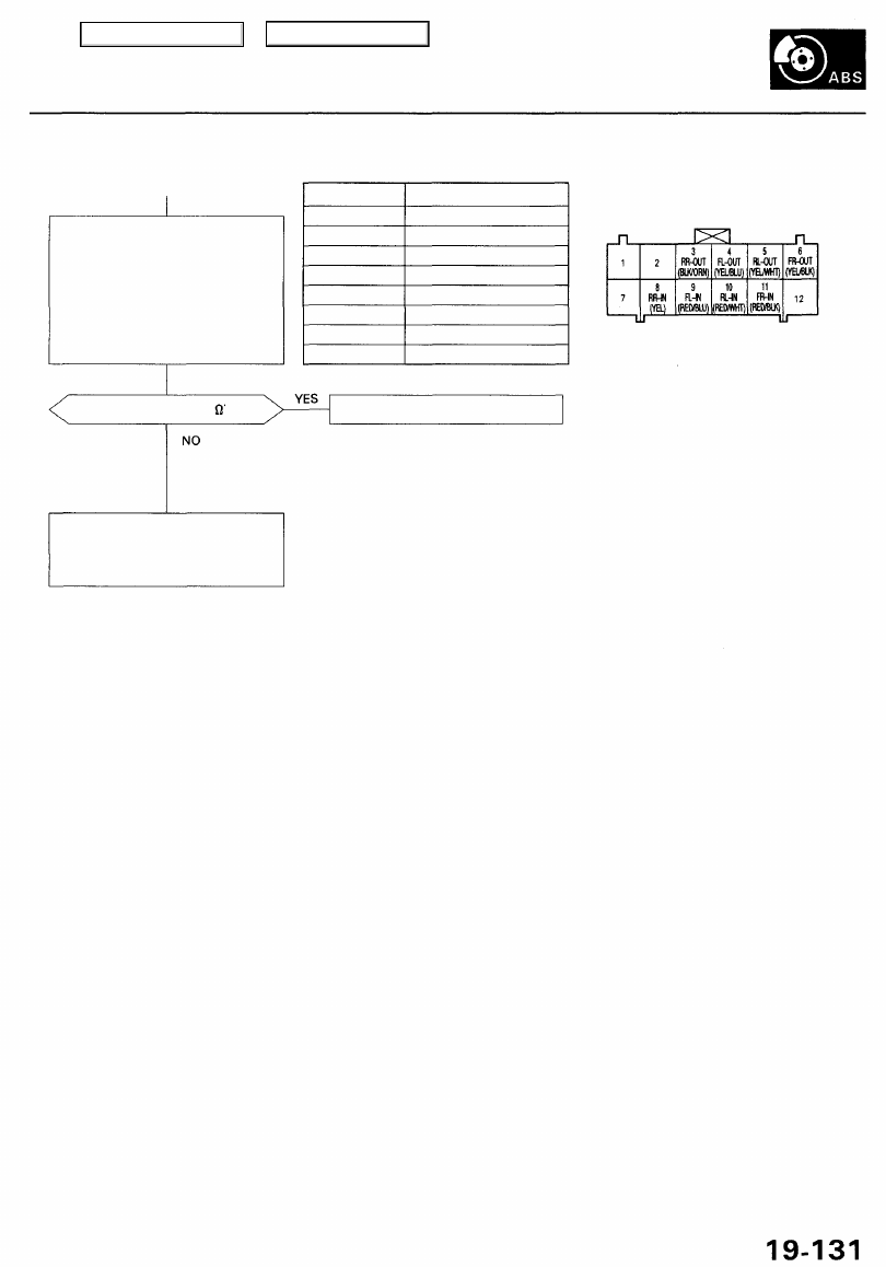
Check for a short to another wire
in the solenoid circuit:
1. Disconnect the modulator
unit connector.
2. Check for continuity between
the appropriate ABS control
unit 12P connector terminal
and all other solenoid circuit
terminals (see table).
Is there continuity?
DTC
31: FR-IN
32: FR-OUT
33: FL-IN
34: FL-OUT
35: RR-IN
36: RR-OUT
37: RL-IN
38: RL-OUT
Appropriate Terminal
ABS control
unit 12P
connector
No. 11
No. 6
No. 9
No. 4
No. 8
No. 3
No. 10
No. 5
Modulator
unit
connector
No. 1
No. 5
No. 4
No. 8
No. 3
No. 7
No. 2
No. 6
Repair open in the appropriate
solenoid circuit wire between
the ABS control unit and the
modulator unit.
JUMPER WIRE
Terminal side of female terminals
ABS CONTROL UNIT 12P CONNECTOR
Wire colors of fail-safe relay connector:
BRN/BLK, WHT/GRN, BLK, YEL/GRN
Replace the modulator unit.
Wire side of female terminals
FAIL-SAFE RELAY CONNECTOR
JUMPER
WIRE
Terminal side of female terminals
ABS CONTROL UNIT 12P CONNECTOR
Replace the modulator unit.
Wire side of female terminals
Check for an open in the solenoid:
1. Remove the jumper wire from
the modulator unit connector.
2. Connect the modulator unit
connector.
3. Connect the fail-safe relay con-
nector terminal No. 1 to body
ground with a jumper wire.
4. Check the resistance between
the appropriate ABS control
unit 12P connector terminal
and body ground (see table).
MODULATOR UNIT CONNECTOR
Main Menu
Table of Contents
Check for a short to another wire
in the solenoid:
1. Connect the modulator unit
connector.
2. Check for continuity between
the appropriate ABS control
unit 12P connector terminal
and all other solenoid circuit
terminals (see table).
DTC
31: FR-IN
32: FR-OUT
33: FL-IN
34: FL-OUT
35: RR-IN
36: RR-OUT
37: RL-IN
38: RL-OUT
Appropriate Terminal
No. 11
No. 6
No. 9
No. 4
No. 8
No. 3
No. 10
No. 5
Is there less than 3 ?
ABS CONTROL UNIT 12P CONNECTOR
Wire side of female terminals
Replace the modulator unit.
Check for loose ABS control unit
connectors. If necessary, substi-
tute a known-good ABS control
unit and recheck.
Main Menu
Table of Contents
Troubleshooting
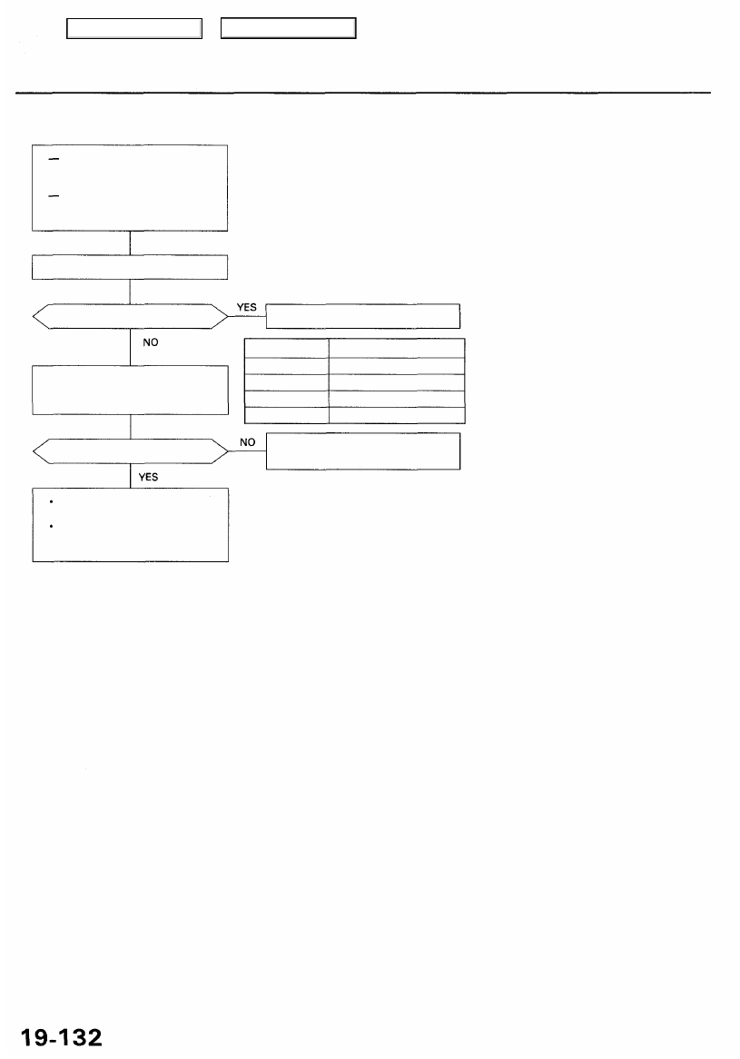
DTC 41, 42, 43, 44: Wheel Lock
Do the brakes drag?
Repair the brake drag.
Check the installation of the
appropriate wheel sensor (see
table).
DTC
41
42
43
44
Appropriate Wheel Sensor
Right-front
Left-front
Right-rear
Left-rear
Is it correct?
Reinstall the wheel sensor cor-
rectly.
The probable cause was the
vehicle spun during cornering.
If the problem occurs again,
check the modulator using the
Honda PGM Tester.
While driving and pressing the
brake pedal, the ABS indicator
comes on.
With the SCS service connector
connected (see page
),
DTCs 41-44 are indicated.
Check for brake drag.
Main Menu
Table of Contents
Нет комментариевНе стесняйтесь поделиться с нами вашим ценным мнением.
Текст