Acura RL (1996-2004 year). Manual — part 529
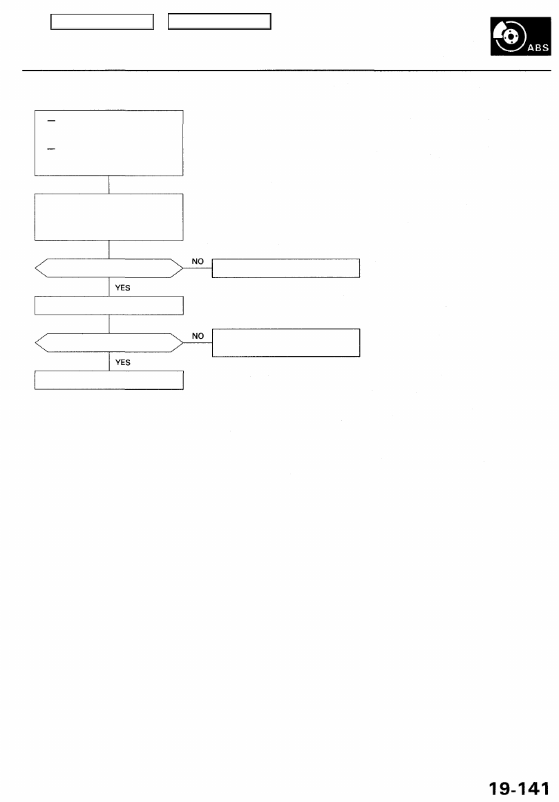
DTC 61, 62: Ignition Voltage
With the ignition switch ON
(II), the ABS indicator comes
on.
With the SCS service connec-
tor connected (see page
), DTC 61, 62 are indicated.
Problem verification:
1. Erase the DTC.
2. Test-drive the vehicle at 6 mph
(10 km/h) or more.
Does the ABS indicator come on?
Verify the DTC.
Is DTC 61 or 62 indicated?
The system is OK at this time.
Perform the appropriate trou-
bleshooting for the code.
Check the charging system.
Main Menu
Table of Contents
Troubleshooting
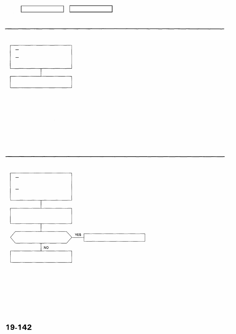
DTC 71: Different Diameter Tire
While driving the vehicle, the
ABS indicator comes on.
With the SCS service connec-
tor connected (see page
), DTC 71 is indicated.
Replace the tire(s) with the spec-
ified size.
DTC 81: Central Processing Unit (CPU)
Does the ABS indicator come
on and is DTC 81 indicated?
Replace the ABS control unit.
Intermittent failure; the vehicle is
OK at this time.
Problem verification:
1. Erase the DTC.
2. Test-drive the vehicle.
With the ignition switch ON
(II), the ABS indicator does
not go off.
With the SCS service connec-
tor connected (see page
), DTC 81 is indicated.
Main Menu
Table of Contents
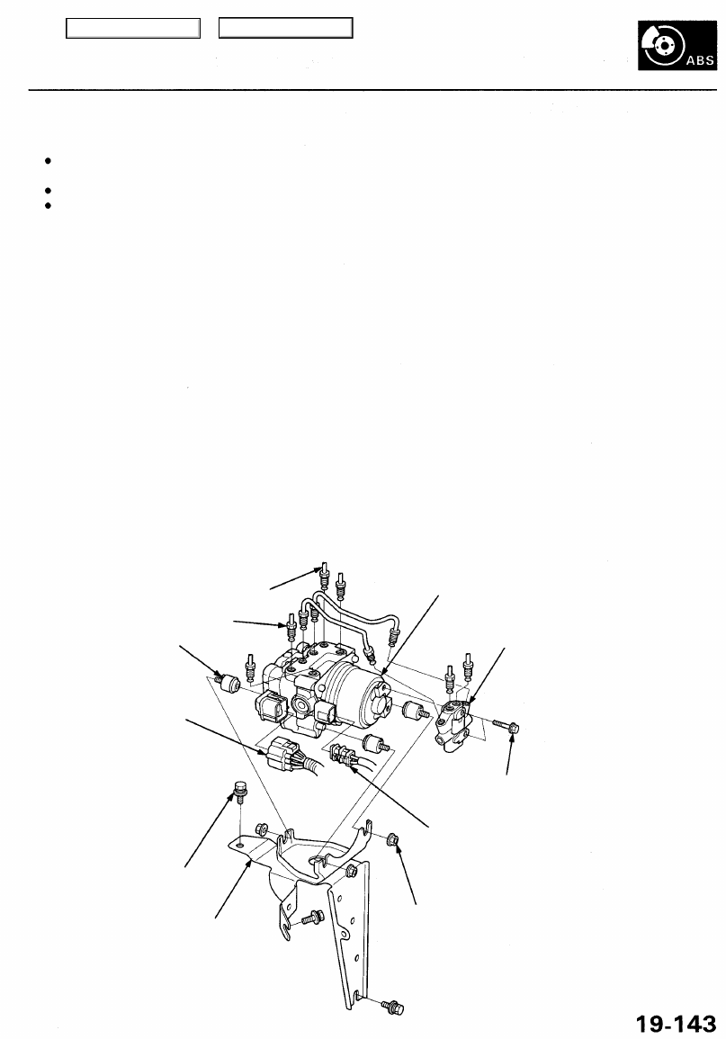
Modulator Unit
Removal/Installation
NOTE:
Do not spill brake fluid on the vehicle; it may damage the paint; if brake fluid does not contact the paint, wash it off
immediately with water.
Take care not to damage or deform the brake lines during removal and installation.
To prevent the brake fluid from flowing, plug and cover the hose ends and joints with a shop towel or equivalent mate-
rial.
Removal
1. Disconnect the modulator unit and pump motor connectors.
2. Disconnect the brake lines, then remove the proportioning control valve.
3. Remove the modulator unit.
Installation
1. Install the modulator unit.
2. Install the proportioning control valve, then connect the brake lines. Tighten the flare nuts to 15 N-m (1.5 kgf-m, 11 Ibf-ft).
3. Connect the modulator unit and pump motor connectors.
4. Bleed the brake system, starting with the front wheels.
5. Start the engine, and check that the ABS indicator goes off.
6. Test-drive the vehicle, and check that the ABS indicator does not come on.
From
From left-front
right-front
MODULATOR UNIT
RUBBER MOUNT
MODULATOR UNIT
CONNECTOR
8 mm BOLT
22 N-m (2.2 kgf-m, 16 Ibf-ft)
BRACKET
PROPORTIONING
CONTROL VALVE
6 mm BOLT
9.8 N-m (1.0 kgf-m, 7.2 Ibf-ft)
PUMP MOTOR CONNECTOR
6 mm NUT
9.8 N-m (1.0 kgf-m, 7.2 Ibf-ft)
Main Menu
Table of Contents
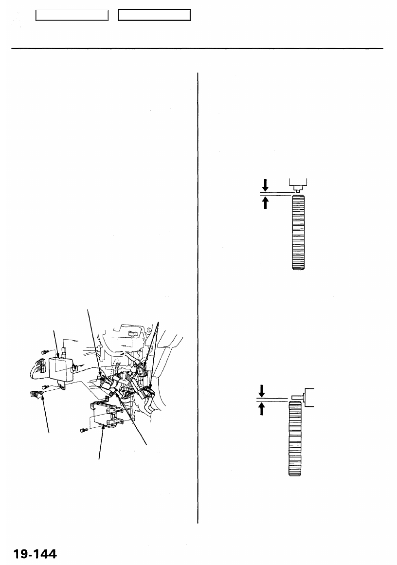
ABS Control Unit
Pulsers/Wheel Sensors
Removal/Installation
1. Remove the glove box.
2. Remove the glove box back cover.
3. Remove the right front door trim.
4. Remove the right kick panel.
5. Turn up the floor mat.
6. Remove the PCM cover.
7. Remove the connectors inside of the right kick
panel.
8. Remove the harness clip A form the ABS control
unit, then remove the bolt at lower side of the ABS
control unit.
9. Remove the multiplex control unit (passenger's).
10. Remove the harness clip B and C.
11. Remove the bolt at rear of the ABS control unit,
then pull out the ABS control unit.
HARNESS CLIP B
CONNECTORS
(Inside the
right kick panel.)
ABS CONTROL UNIT
HARNESS
CLIP A
HARNESS CLIP C
MULTIPLEX CONTROL
UNIT (PASSENGER'S)
12. Install the ABS control unit in the reverse order of
removal.
Inspection
1. Check the front and rear pulser for chipped or dam-
aged teeth.
2. Measure the air gap between the wheel sensor and
pulser all the way around while rotating the pulser.
If the gap exceeds 1.0 mm (0.04 in), check for a bent
suspension arm.
Rear
Remove the rear brake disc to inspect the rear wheel
sensor air gap.
Front
Main Menu
Table of Contents
Нет комментариевНе стесняйтесь поделиться с нами вашим ценным мнением.
Текст