Acura RL (1996-2004 year). Manual — part 556
DTC 93: Throttle Position Sensor/Steering Angle Sensor
NOTE: When both the VSA indicator and the MIL are ON, troubleshoot the PGM-FI system first.
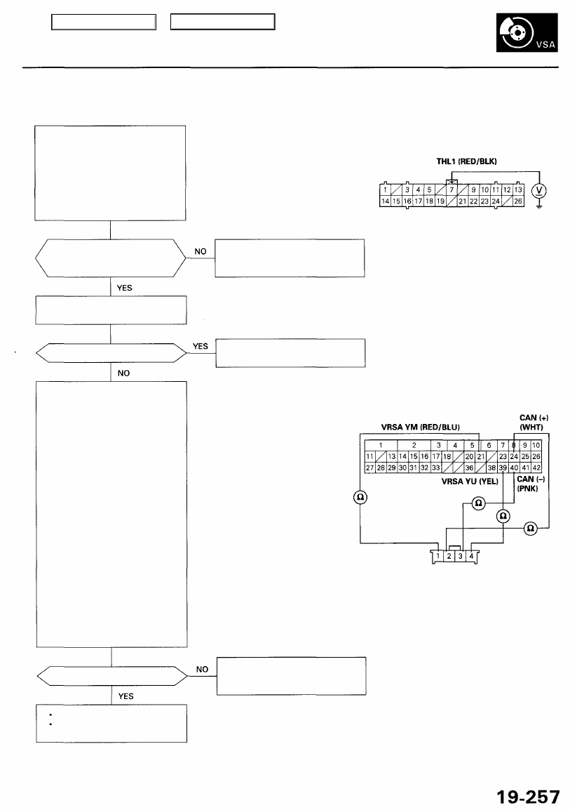
Check for an open in the THL1
circuit:
1. Turn the ignition switch ON (II).
2. Measure the voltage between
the VSA converter unit 26P
connector terminal No. 7 and
body ground when the throt-
tle valve is fully closed and
fully open.
Is the voltage as specified?
— Fully closed: about 0.5 V
— Fully open: about 4.5 V
Check the steering angle sensor
4P connector connection.
Is the connector disconnected?
Check for an open in the steering
angle sensor circuits:
1. Turn the ignition switch OFF.
2. Disconnect the VSA control
unit 42P connector and the
steering angle sensor 4P con-
nector.
3. Check for continuity between
the VSA control unit 42P con-
nector terminal No. 39 and
the steering angle sensor 4P
connector terminal No. 4.
4. Check for continuity between
the VSA control unit 42P con-
nector terminal No. 21 and
the steering angle sensor 4P
connector terminal No. 1.
5. Check for continuity between
the VSA control unit 42P con-
nector terminal No. 24 and
the steering angle sensor 4P
connector terminal No. 2.
6. Check for continuity between
the VSA control unit 42P con-
nector terminal No. 40 and
the steering angle sensor 4P
connector terminal No. 3.
Is there continuity?
The system is OK at this time.
If the problem recurs, replace
the VSA converter unit.
VSA CONVERTER UNIT 26P CONNECTOR
Repair open in the wire between
the PCM and the VSA converter
unit.
Connect the steering angle sen-
sor 4P connector.
VSA CONTROL UNIT 42P CONNECTOR
Wire side of female terminals
STEERING ANGLE SENSOR 4P CONNECTOR
Wire side of female terminals
Repair open in the wire between
the steering angle sensor and
the VSA control unit.
Wire side of female terminals
YRSA YM
(RED/WHT)
CAN (-)
(WHT)
CAN (+) (RED)
YRSA YU
(RED/BLU)
Main Menu
Table of Contents
Troubleshooting
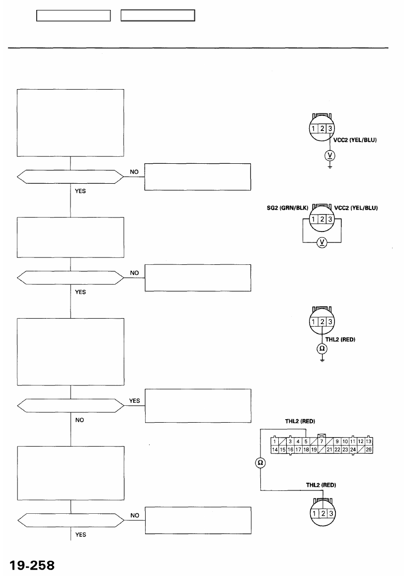
DTC 94: TCS Control Valve Sensor
NOTE: When both the VSA system indicator and the MIL are ON, troubleshoot the PGM-FI system first.
Check for an open in the VCC2
circuit:
1. Disconnect the TCS control
valve sensor 3P connector.
2. Turn the ignition switch ON (II).
3. Measure the voltage between
the TCS control valve sensor
3P connector terminal No. 3
and body ground.
Is there about 5 V?
Check for an open in the SG2 cir-
cuit:
Measure the voltage between the
TCS control valve sensor 3P con-
nector terminal No. 1 and No. 3.
Is there about 5 V?
Check for a short to body ground
in the THL2 circuit:
1. Turn the ignition switch OFF.
2. Disconnect the VSA converter
unit 26P connector.
3. Check for continuity between
the TCS control valve sensor
3P connector terminal No. 2
and body ground.
Is there continuity?
Check for an open in the THL2
circuit:
Check for continuity between the
VSA converter unit 26P connec-
tor terminal No. 5 and the TCS
control valve sensor 3P connec-
tor terminal No. 2.
Is there continuity?
TCS CONTROL VALVE
SENSOR 3P CONNECTOR
Repair open in the wire between
the PCM and the TCS control
valve sensor.
Wire side of female terminals
Repair open in the wire between
the PCM and the TCS control
valve sensor.
Repair short to body ground in
the wire between the TCS con-
trol valve sensor and the VSA
converter unit.
VSA CONVERTER UNIT 26P CONNECTOR
Wire side of female terminals
Repair open in the wire between
the TCS control valve sensor and
the VSA converter unit.
Main Menu
Table of Contents
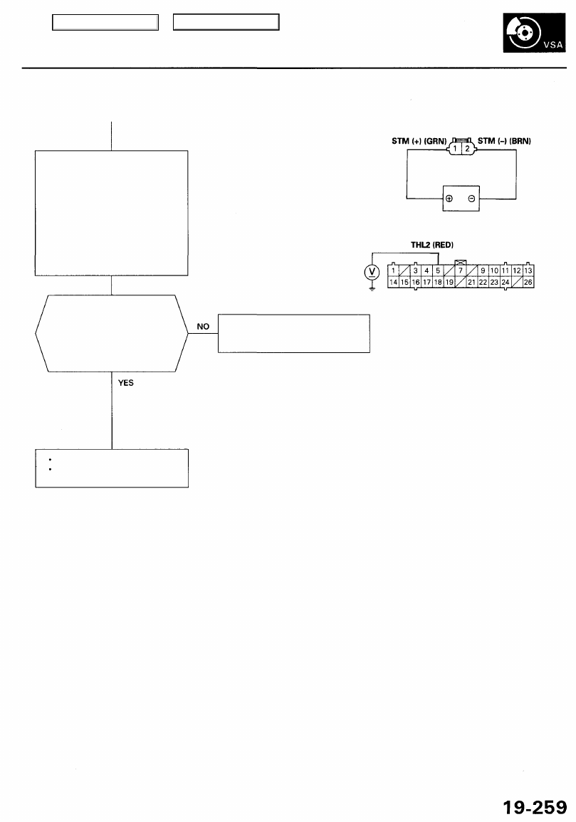
Check the TCS control valve sen-
sor:
1. Remove the intake air duct
).
2. Turn the ignition switch ON
(II).
3. Connect the battery and TCS
control valve actuator.
4. Measure the voltage between
the VSA converter unit 26P
connector terminal No. 5 and
body ground.
TCS CONTROL VALVE
ACTUATOR 2P CONNECTOR
Terminal side of
male terminals
BATTERY
CAUTION:
• Be careful not to short the terminals.
• After checking, disconnect the terminals.
VSA CONVERTER 26P CONNECTOR
Is the voltage as specified?
— Fully closed: about 0.5 V
— Fully open: about 4.5 V
NOTE: There should be a smooth
transition from about 4.5 V to
0.5 V as the TCS control valve is
closed.
Wire side of female terminals
Replace the TCS control valve
sensor (faulty TCS control valve
sensor).
The system is OK at this time.
If the problem recurs, replace
the VSA converter unit.
Main Menu
Table of Contents
Troubleshooting
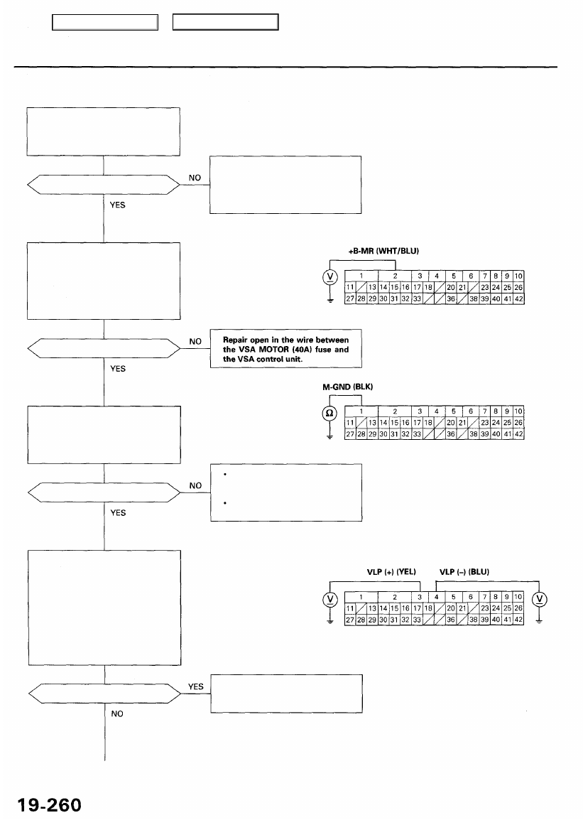
DTC 95: Precharge Pump Motor
Check the VSA MOTOR (40A)
fuse in the under-hood fuse/relay
box, and reinstall the fuse if it is
OK.
Is the fuse OK?
Check for an open in the +B-MR
circuit:
1. Disconnect VSA control unit
42P connector.
2. Measure the voltage between
terminal No. 2 and body
ground.
Is there battery voltage?
Check for an open in the M-GND
circuit:
Check for continuity between the
VSA control unit 42P connector
terminal No. 1 and body ground.
Is there continuity?
Check for a short to power in the
VLP circuits:
1. Disconnect the precharge
pump motor 2P connector.
2. Turn the ignition switch ON
(II).
3. Measure the voltage between
body ground and the VSA
control unit 42P connector
terminals No. 3 and No. 4
individually.
Is there battery voltage?
Replace the fuse, and recheck.
If the fuse is blown, check for a
short to body ground in this fuse
circuit. If the circuit is OK, replace
the VSA modulator-control unit.
VSA CONTROL UNIT 42P CONNECTOR
Repair open in the wire
between the VSA control unit
and body ground.
Repair poor ground (G401,
G402).
Repair short to power in the wire
between the precharge pump
motor and the VSA control unit.
Wire side of female terminals
Main Menu
Table of Contents
Нет комментариевНе стесняйтесь поделиться с нами вашим ценным мнением.
Текст