Acura RL (1996-2004 year). Manual — part 554
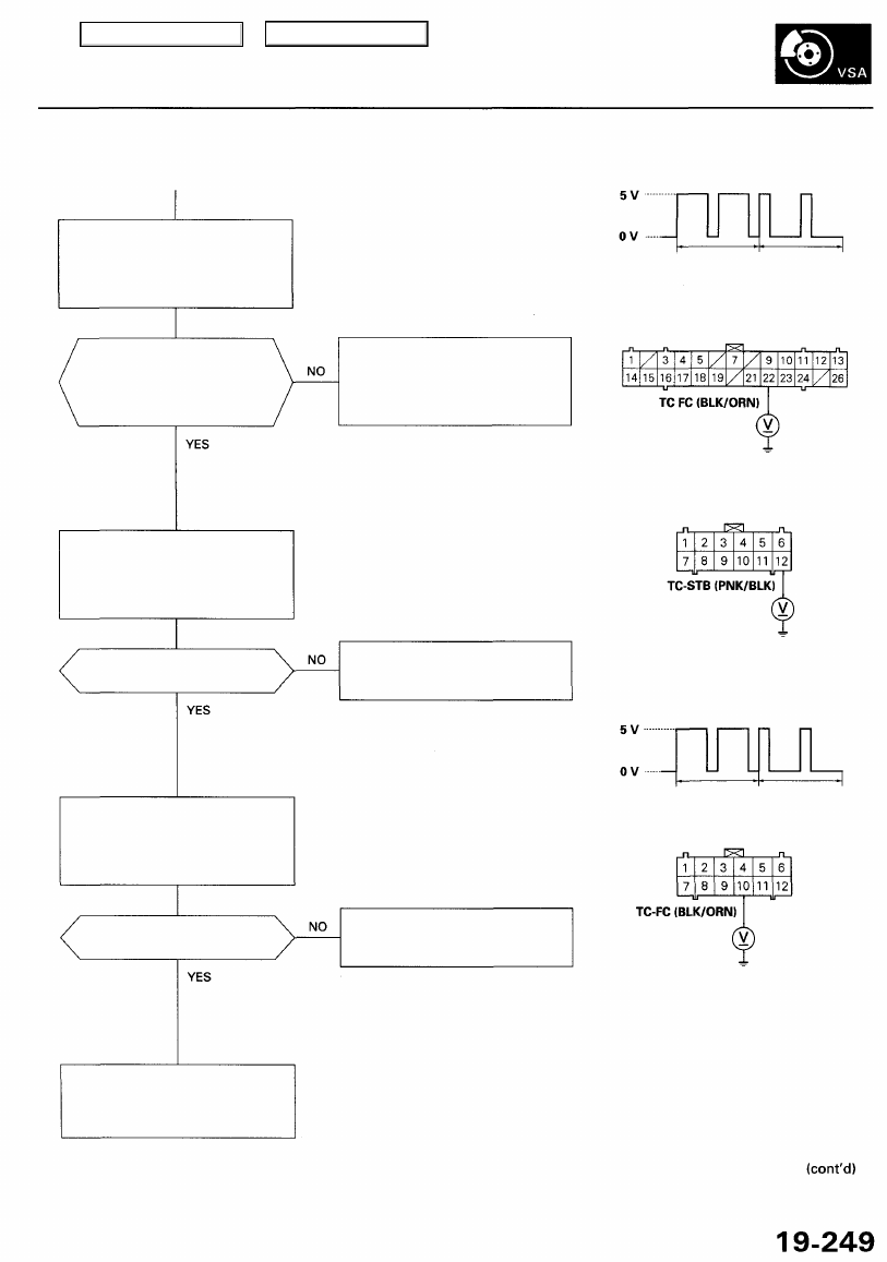
Check the VSA converter unit
(TC FC):
Measure the voltage between the
VSA converter unit 26P connector
terminal No. 22 and body ground.
NOTE: Use the 10 V range or a similar
range in an analog tester.
VSA IS NOT VSA IS
FUNCTIONING FUNCTIONING
VSA CONVERTER UNIT 26P CONNECTOR
Is the voltage as specified?
— VSA is functioning (maximum):
about 1.5V
— VSA is not functioning: about
4.5V
Check for loose terminals in the
VSA converter unit 26P connec-
tor. If necessary, substitute a
known-good VSA converter unit,
and recheck.
NOTE: Stop the wheels by pressing the
brake pedal lightly.
Check for an open in the TC STB
circuit:
Measure the voltage between the
PCM connector C (12P) terminal
No. 12 and body ground.
Wire side of female terminals
PCM CONNECTOR C (12P)
Is there about 5 V when
VSA is not functioning?
Repair open in the wire between
the VSA converter unit and the
PCM.
Wire side of female terminals
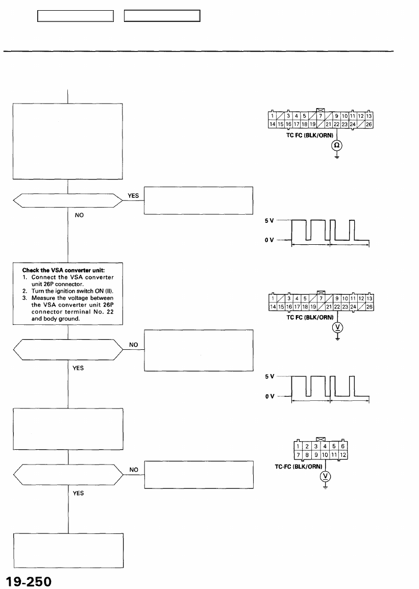
Check for an open in the TC FC
circuit:
Measure the voltage between the
PCM connector C (12P) terminal
No. 10 and body ground.
NOTE: Use the 10 V range or a similar range
in an analog tester.
VSA IS NOT VSA IS
FUNCTIONING FUNCTIONING
Is there about 4.5 V when
VSA is not functioning?
Repair open in the wire between
the VSA converter unit and the
PCM.
Check for loose terminals in the
PCM connectors. If necessary,
substitute a known-good PCM,
and recheck.
Main Menu
Table of Contents
Troubleshooting
DTC 83: VSA Inhibition (cont'd)
Check for a short to body ground
in the TC FC circuit:
1. Turn the ignition switch OFF.
2. Disconnect the PCM connec-
tor C (12P) and the VSA con-
verter unit 26P connector.
3. Check for continuity between
the VSA converter unit 26P
connector terminal No. 22
and body ground.
Is there continuity?
Is there about 4.5 V when
VSA is not functioning?
Check for an open in the TC FC
circuit:
Measure the voltage between the
PCM connector C (12P) terminal
No. 10 and body ground.
Is there about 4.5 V when
VSA is not functioning?
Check for loose terminals in the
PCM connectors. If necessary,
substitute a known-good PCM,
and recheck.
VSA CONVERTER UNIT 26P CONNECTOR
Wire side of female terminals
Repair short to body ground in
the wire between the PCM and
the VSA converter unit.
VSA IS NOT VSA IS
FUNCTIONING FUNCTIONING
NOTE: Use the 10 V range or a similar
range in an analog tester.
Check for loose terminals in the
VSA converter unit 26P connector.
If necessary, substitute a known-
good VSA converter unit, and
recheck.
NOTE: Use the 10 V range or a similar
range in an analog tester.
VSA IS NOT VSA IS
FUNCTIONING FUNCTIONING
PCM CONNECTOR C (12P)
Repair open in the wire between
the PCM and the VSA converter
unit.
Wire side of female terminals
Main Menu
Table of Contents
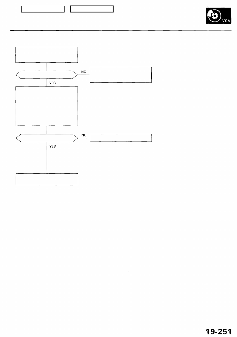
DTC 84: Steering Angle Sensor Neutral Position
Perform the steering angle sen-
sor neutral position check proce-
dure (see page
).
Is it OK?
Perform the steering angle sen-
sor neutral position memorizing
procedure (see page
).
Check the steering angle sensor:
1. Substitute a known-good
steering angle sensor.
2. Connect all of disconnected
connector.
3. Clear the DTC.
4. Test-drive the vehicle around
a number of corners.
5. Verify the DTC.
Is the DTC 84 indicated?
Replace the steering angle sensor.
Replace the VSA modulator-
control unit.
Main Menu
Table of Contents
Troubleshooting
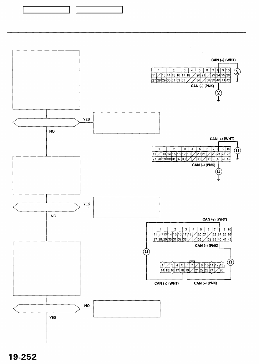
DTC 86: CAN Bus Circuit
Check for a short to power in the
CAN circuits:
1. Disconnect the VSA converter
unit 26P connector, steering
angle sensor 4P connector
and the VSA control unit 42P
connector.
2. Turn the ignition switch ON (II).
3. Measure the voltage between
body ground and the VSA
control unit 42P connector
terminal No. 24 and No. 40
individually.
Is there battery voltage?
VSA CONTROL UNIT 42P CONNECTOR
Wire side of female terminals
Repair short to power in the wire
between the steering angle sen-
sor, VSA converter unit, and the
VSA control unit.
Repair short to body ground in
the wire between the steering
angle sensor, VSA converter
unit, and the VSA control unit.
Wire side of female terminals
Repair open in the wire between
the VSA control unit and the
VSA converter unit.
VSA CONVERTER UNIT 26P CONNECTOR
Is there continuity?
Check for an open in the CAN cir-
cuits (converter side):
1. Check for continuity between
the VSA control unit 42P con-
nector terminal No. 24 and
the VSA converter unit 26P
connector terminal No. 18.
2. Check for continuity between
the VSA control unit 42P con-
nector terminal No. 40 and
the VSA converter unit 26P
connector terminal No. 19.
Is there continuity?
Check for a short to body ground
in the CAN circuits:
1. Turn the ignition switch OFF.
2. Check for continuity between
body ground and the VSA
control unit 42P connector
terminal No. 24 and No. 40
individually.
Main Menu
Table of Contents
Нет комментариевНе стесняйтесь поделиться с нами вашим ценным мнением.
Текст