Acura RL (1996-2004 year). Manual — part 557
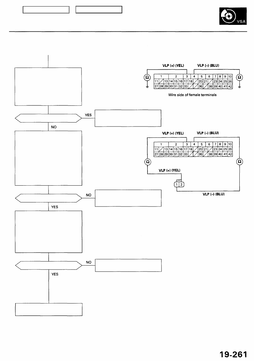
Check for a short to body ground
in the VLP circuits:
1. Turn the ignition switch OFF.
2. Check for continuity between
body ground and the VSA
control unit 42P connector
terminals No. 3 and No. 4
individually.
Is there continuity?
Check for an open in the VLP cir-
cuits:
1. Check for continuity between
the VSA control unit 42P con-
nector terminal No. 3 and the
precharge pump motor 2P
connector terminal No. 2.
2. Check for continuity between
the VSA control unit 42P con-
nector terminal No. 4 and the
precharge pump motor 2P
connector terminal No. 1.
Is there continuity?
Check the precharge pump
motor:
1. Substitute a known-good
precharge pump motor.
2. Connect all of disconnected
connector.
3. Clear the DTC.
4. Test-drive the vehicle.
5. Verify the DTC.
Is DTC 95 indicated?
VSA CONTROL UNIT 42P CONNECTOR
Repair short to body ground in the
wire between the precharge pump
motor and the VSA control unit.
Repair open in the wire between
the precharge pump motor and
the VSA control unit.
Wire side of
female terminals
Replace the precharge pump
motor.
Replace the VSA modulator-
control unit.
PRECHARGE PUMP MOTOR
2P CONNECTOR
Main Menu
Table of Contents
Troubleshooting
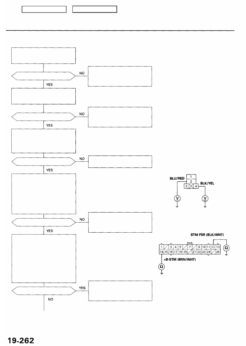
DTC 96, 97: TCS Control Valve Actuator
Check the TCS (20A) fuse in the
under-hood fuse/relay box, and
reinstall the fuse if it is OK.
Is the fuse OK?
Check the ECU (20A) fuse in the
under-dash fuse relay box, and
reinstall the fuse if it is OK.
Is the fuse OK?
Check the sub throttle motor fail-
safe relay in the under-hood
relay box C, and leave the fail-
safe relay removed (see
).
Is the relay OK?
Check for an open in the sub
throttle motor fail-safe relay +B
circuit:
1. Turn the ignition switch ON (II).
2. Measure the voltage between
body ground and the sub
throttle motor fail-safe relay
4P connector terminals No. 2
and No. 4 individually.
Is there battery voltage?
Check for a short to body ground
in the sub throttle motor fail-safe
relay circuit:
1. Turn the ignition switch OFF.
2. Disconnect the VSA converter
unit 26P connector.
3. Check for continuity between
body ground and the VSA
converter unit 26P connector
terminals No. 12 and No. 14
individually.
Is there continuity?
Replace the fuse and recheck.
If the fuse is blown, check for a
short to body ground in this fuse
circuit.
Replace the fuse and recheck.
If the fuse is blown, check for a
short to body ground in this fuse
circuit.
Replace the sub throttle motor
fail-safe relay.
SUB THROTTLE MOTOR FAIL-SAFE
RELAY 4P CONNECTOR
Repair open in the wire between
the sub throttle motor fail-safe
relay and TCS (20A) fuse or ECU
(20A) fuse.
Wire side of female terminals
VSA CONVERTER UNIT 26P CONNECTOR
Wire side of female terminals
Repair short to body ground in
the wire between the sub throt-
tle motor fail-safe relay and the
VSA converter unit.
Main Menu
Table of Contents
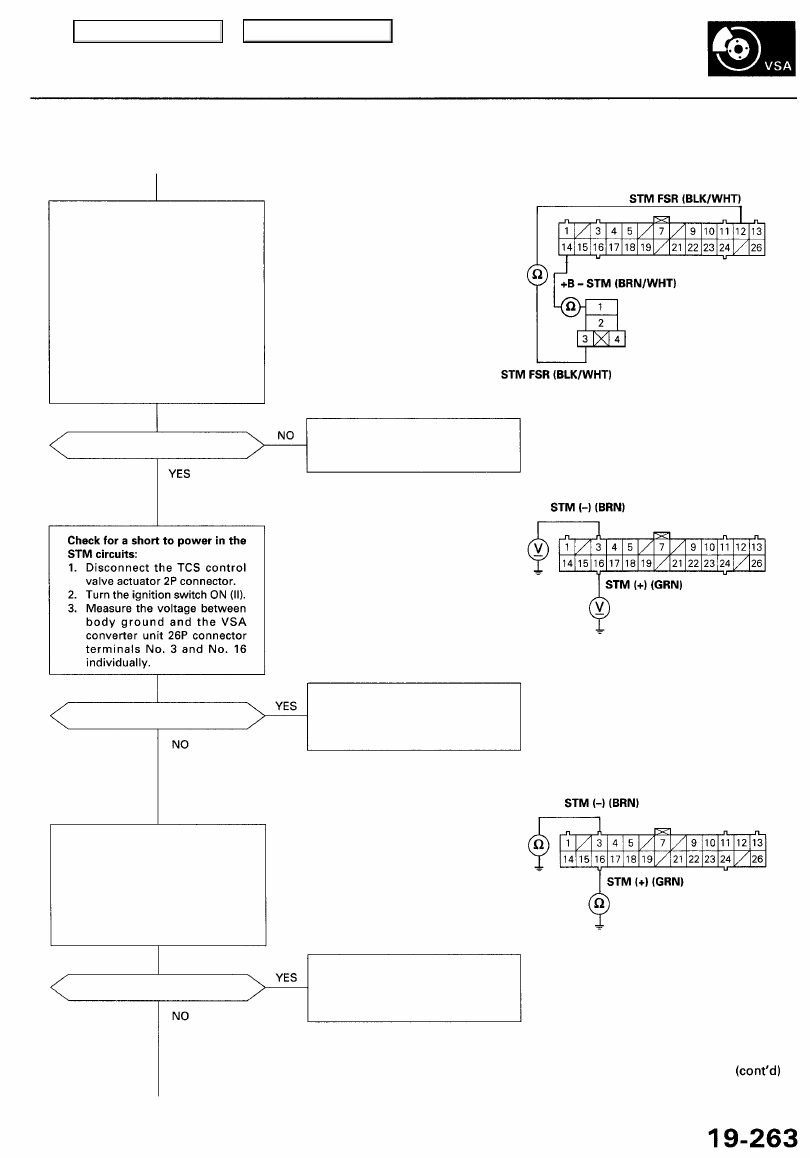
Check for an open in the fail-safe
relay circuits:
1. Check for continuity between
the VSA converter unit 26P
connector terminal No. 12
and the sub throttle motor
fail-safe relay 4P connector
terminal No. 3.
2. Check for continuity between
the VSP control unit 26P con-
nector terminal No. 14 and the
sub throttle motor fail-safe
relay 4P connector terminal
No. 1.
Is there continuity?
Is there battery voltage?
Check for short to body ground
in the STM circuits:
1. Turn the ignition switch OFF.
2. Check for continuity between
body ground and the VSA
converter unit 26P connector
terminals No. 3 and No. 16
individually.
Is there continuity?
(To page
VSA CONVERTER UNIT 26P CONNECTOR
Wire side of female terminals
Repair open in the wire between
the fail-safe relay and the VSA
control unit.
SUB THROTTLE MOTOR
FAIL-SAFE RELAY
4P CONNECTOR
Wire side of female terminals
VSA CONVERTER UNIT 26P CONNECTOR
Wire side of female terminals
Repair short to power in the wire
between the TCS control valve
actuator and the VSA converter
unit.
Repair short to body ground in
the wire between the TCS con-
trol valve actuator and the VSA
converter unit.
Main Menu
Table of Contents
Troubleshooting
DTC 96, 97: TCS Control Valve Actuator (cont'd)
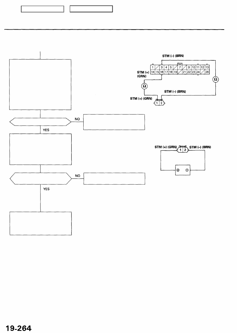
VSA CONVERTER UNIT 26P CONNECTOR
Check for an open in the STM cir-
cuits:
1. Check for continuity between
the VSA converter unit 26P
connector terminal No. 3 and
TCS control valve actuator 2P
connector terminal No. 2.
2. Check for continuity between
the VSA converter unit 26P
connector terminal No. 16 and
TCS control valve actuator 2P
connector terminal No. 1.
Wire side of female terminals
TCS CONTROL VALVE
ACTUATOR 2P CONNECTOR
Is there continuity?
Repair open in the wire between
the TCS control valve actuator
and the VSA converter unit.
Wire side of
female terminals
Check the TCS control valve
operation:
Connect the battery power to the
TCS control valve actuator 2P
connector terminal No. 1, and
ground connector terminal No. 2
for one second.
CAUTION:
• Be careful not to short the terminals.
• After checking, disconnect the termi-
nals.
TCS CONTROL VALVE
ACTUATOR 2P CONNECTOR
Does the TCS control valve
operate smoothly?
Replace the TCS control valve
assembly.
Check for loose terminals in the
VSA converter unit 26P connector.
If necessary, substitute a known-
good VSA converter unit, and
recheck.
Terminal side of
male terminals
BATTERY
Main Menu
Table of Contents
Нет комментариевНе стесняйтесь поделиться с нами вашим ценным мнением.
Текст