Acura RL (1996-2004 year). Manual — part 539
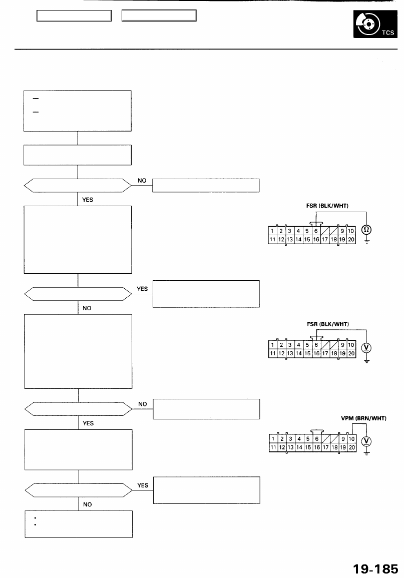
Fail-safe Relay
Diagnostic Trouble Code (DTC) 5-1: Fail-safe Relay Diagnosis
With engine running, TCS
indicator light is ON.
With the SCS service connec-
tor connected (see page
), DTC 5-1 is indicated.
Remove the fail-safe relay, and
).
Is the relay OK?
Check for a short to body ground
in the FSR circuit:
1. Disconnect the fail-safe relay
and TCS control unit 20P con-
nectors.
2. Check for continuity between
the TCS control unit 20P con-
nector terminal No. 6 and body
ground.
Is there continuity?
Check the FSR circuit inside the
TCS control unit:
1. Connect the fail-safe relay and
TCS control unit 20P connec-
tors.
2. Turn the ignition switch ON (II).
3. Measure the voltage between
the TCS control unit 20P con-
nector terminal No. 6 and body
ground.
Is there battery voltage?
Check for a short to power in the
VPM circuit:
Measure the voltage between the
TCS control unit 20P connector
terminal No. 10 and body ground.
Is there battery voltage?
The system is OK at this time.
If the problem recurs, replace
the TCS control unit.
Replace the fail-safe relay.
TCS CONTROL UNIT 20P CONNECTOR
Wire side of female terminals
Repair short to body ground in
the wire between the fail-safe
relay and TCS control unit.
Replace the TCS control unit.
(Short circuit inside the unit)
Repair short to power in the wire
between the TCS control unit
and fail-safe relay.
Main Menu
Table of Contents
Troubleshooting
Ignition Switch (IG1) Signal
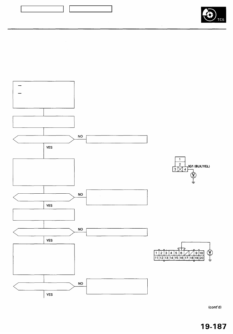
Diagnostic Trouble Code (DTC) 5-2, 5-3: Ignition Switch (IG1) Signal Diagnosis
The TCS control unit constantly monitors the IG1 voltage. When the unit detects IG1 voltage of 12.5 V or less, it turns on
the TCS indicator light and the DTC 5-2 is memorized. When the unit detects IG1 voltage of 19 V or more, it turns on the
TCS indicator light and the DTC 5-3 is memorized.
Possible causes which raise the IG1 voltage to 19 V or more:
Faulty charging system
Excessive voltage from a battery charger
Connection to a 24 V battery by booster cables
Problem verification:
Start the engine.
Does the TCS indicator light
come on?
External factor(s) can be the
cause(s) of the problem. Ask the
user for the condition when the
symptom appears.
Check the charging system (see
).
Main Menu
Table of Contents
TCS Control Valve Actuator
Diagnostic Trouble Code 5-4 : Initial Motor Operation Diagnosis
5-5 : Motor Operation (1) Diagnosis
5-6 : Motor Operation (2) Diagnosis
5-7 : Over Limit Motor Current Diagnosis
5-8 : Motor Driver Open Diagnosis
5-9 : Under Limit Motor Current Diagnosis
5-10: Motor Driver Shorted Diagnosis
With engine running, TCS
indicator light is ON.
With the SCS service connec-
tor connected (see page
), DTC 5-4, 5-5, 5-6, 5-7, 5-8,
5-9 and/or 5-10 are indicated.
Check the TCS (15 A) fuse in the
under-hood fuse/relay box.
Is the fuse OK?
Replace the fuse and recheck.
NOTE: Reinstall the
fuse if it is OK.
Check for an open in the IG1 cir-
cuit:
1. Turn the ignition switch ON (II).
2. Measure the voltage between
the fail-safe relay connector ter-
minal No. 4 and body ground.
NOTE: Start the engine, and recheck the
fuse. If the fuse is blown, check for a
short to body ground in the VPM circuit
between the fail-safe relay and TCS con-
trol unit.
FAIL-SAFE RELAY CONNECTOR
Wire side of female terminals
Is there battery voltage?
Repair open in the wire between
the ECU (20 A) fuse and fail-safe
relay.
Check the fail-safe relay (see
).
Is the relay OK?
Replace the fail-safe relay.
TCS CONTROL UNIT 20P CONNECTOR
FSR (BLK/WHT)
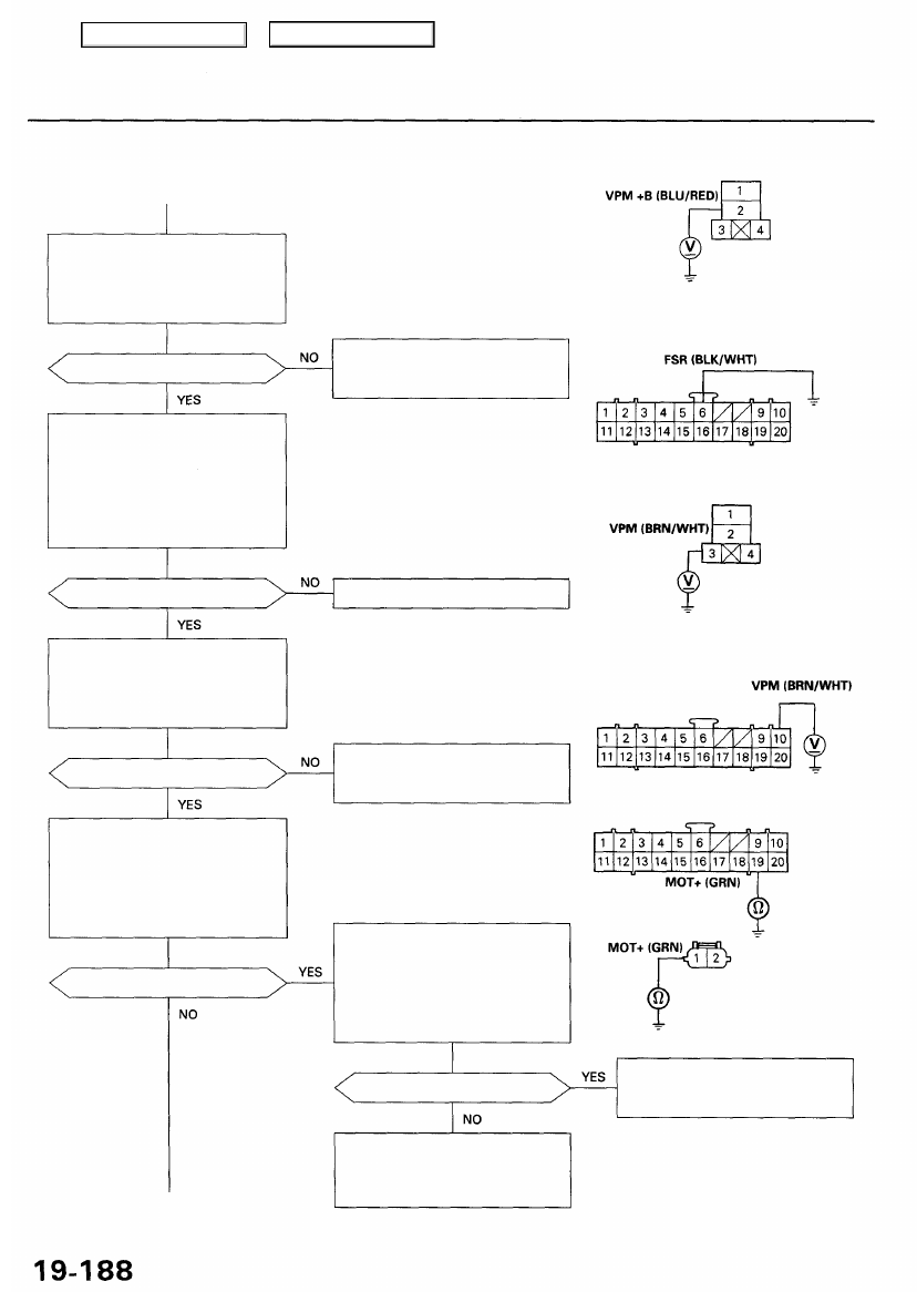
Check for an open in the FSR cir-
cuit:
1. Turn the ignition switch ON (II).
2. Measure the voltage between
the TCS control unit 20P con-
nector terminal No. 6 and body
ground.
Wire side of female terminals
Is there battery voltage?
Repair open in the wire between
the fail-safe relay and TCS con-
trol unit.
Main Menu
Table of Contents
Troubleshooting
TCS Control Valve Actuator (cont'd)
Check for an open in the VPM +B
circuit:
Measure the voltage between the
fail-safe relay connector terminal
No. 2 and body ground.
Is there battery voltage?
Check the fail-safe relay:
1. Connect the TCS control unit
20P connector terminal No. 6
and body ground with a
jumper wire.
2. Measure the voltage between
the fail-safe relay connector ter-
minal No. 3 and body ground.
Is there battery voltage?
Check for an open in the VPM
circuit:
Measure the voltage between the
TCS control unit 20P connector
terminal No. 10 and body ground.
Is there battery voltage?
Check the MOT circuit:
1. Disconnect the jumper wire
and TCS control unit 20P con-
nector.
2. Check for continuity between
terminal No. 19 and body
ground.
Is there continuity?
Repair open in the wire between
the TCS (15 A) fuse and fail-safe
relay.
Replace the fail-safe relay.
Repair open in the wire between
the fail-safe relay and TCS con-
trol unit.
Check for a short to body ground
in the MOT circuit:
1. Disconnect the TCS control
valve actuator connector.
2. Check for continuity between
terminal No. 1 and body
ground.
Is there continuity?
Repair short to body ground in
the MOT+ or MOT- circuit
between the TCS control unit
and TCS control valve actuator.
FAIL-SAFE RELAY CONNECTOR
Wire side of female terminals
TCS CONTROL UNIT 20P CONNECTOR
JUMPER
WIRE
Wire side of female terminals
FAIL-SAFE RELAY CONNECTOR
Wire side of female terminals
TCS CONTROL UNIT 20P CONNECTOR
Wire side of female terminals
TCS CONTROL VALVE
ACTUATOR CONNECTOR
Wire side of female terminals
Replace the TCS control valve
assembly. (Short circuit inside
the motor)
Main Menu
Table of Contents
Нет комментариевНе стесняйтесь поделиться с нами вашим ценным мнением.
Текст