Acura RL (1996-2004 year). Manual — part 537
Reference Voltage (VREF) Signal
Diagnostic Trouble Code (DTC) 3-4: Reference Voltage (VREF) Signal Diagnosis
With engine running, TCS indi-
cator light is ON.
With the SCS service connec-
tor connected (see page
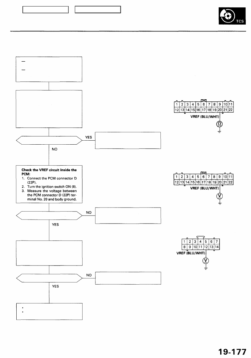
Check for a short to body ground
in the VREF circuit:
1. Disconnect the PCM connec-
tor D (22P) and TCS control
unit 14P connectors.
2. Check for continuity between
the PCM connector D (22P) ter-
minal No. 20 and body ground.
Is there continuity?
Is there about 5 V?
Check for an open in the VREF
circuit:
Measure the voltage between the
TCS control unit 14P connector
terminal No. 12 and body ground.
Is there about 5 V?
The system is OK at this time.
If the problem recurs, replace
the TCS control unit.
PCM CONNECTOR D (22P)
Repair short to body ground in
the wire between the PCM and
TCS control unit.
Wire side of female terminals
Check for loose PCM connectors.
If necessary, substitute a known-
good PCM and recheck.
TCS CONTROL UNIT 14P CONNECTOR
Repair open in the wire between
the PCM and TCS control unit.
Wire side of female terminals
Main Menu
Table of Contents
Troubleshooting
Barometric Pressure (BARO) Signal
Diagnostic Trouble Code (DTC) 3-5: Barometric Pressure (BARO) Signal Diagnosis
With engine running, TCS indi-
cator light is ON.
MIL is OFF.
With the SCS service connec-
tor connected (see page
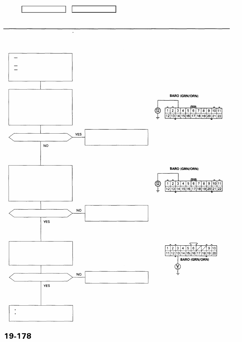
Check for a short to body ground
in the BARO circuit:
1. Disconnect the PCM connector
D (22P) and TCS control unit
20P connectors.
2. Check for continuity between
the PCM connector D (22P) ter-
minal No. 3 and body ground.
Is there continuity?
Check the BARO circuit inside
the PCM:
1. Connect the PCM connector
D (22P).
2. Turn the ignition switch ON (II).
3. Measure the voltage between
the PCM connector D (22P) ter-
minal No. 3 and body ground.
Is there about 3 V?
Check for an open in the BARO
circuit:
Measure the voltage between the
TCS control unit 20P connector
terminal No. 13 and body ground.
Is there about 3 V?
The system is OK at this time.
If the problem recurs, replace
the TCS control unit.
NOTE: When both the TCS indicator
light and the MIL are ON, troubleshoot
the PGM-FI system first.
PCM CONNECTOR D (22P)
Wire side of female terminals
Repair short to body ground in
the wire between the PCM and
TCS control unit.
Check for loose PCM connectors.
If necessary, substitute a known-
good PCM and recheck.
TCS CONTROL UNIT 20P CONNECTOR
Repair open in the wire between
the PCM and TCS control unit.
Wire side of female terminals
Main Menu
Table of Contents
Throttle Position Sensor (TPS) Signal
Diagnostic Trouble Code (DTC) 3-6: Throttle Position Sensor (TPS) Signal Diagnosis
With engine running, TCS
indicator light is ON.
MIL is OFF.
With the SCS service connec-
tor connected (see page
NOTE: When both the TCS indicator
light and the MIL are ON, trouble-
shoot the PGM-FI system first.
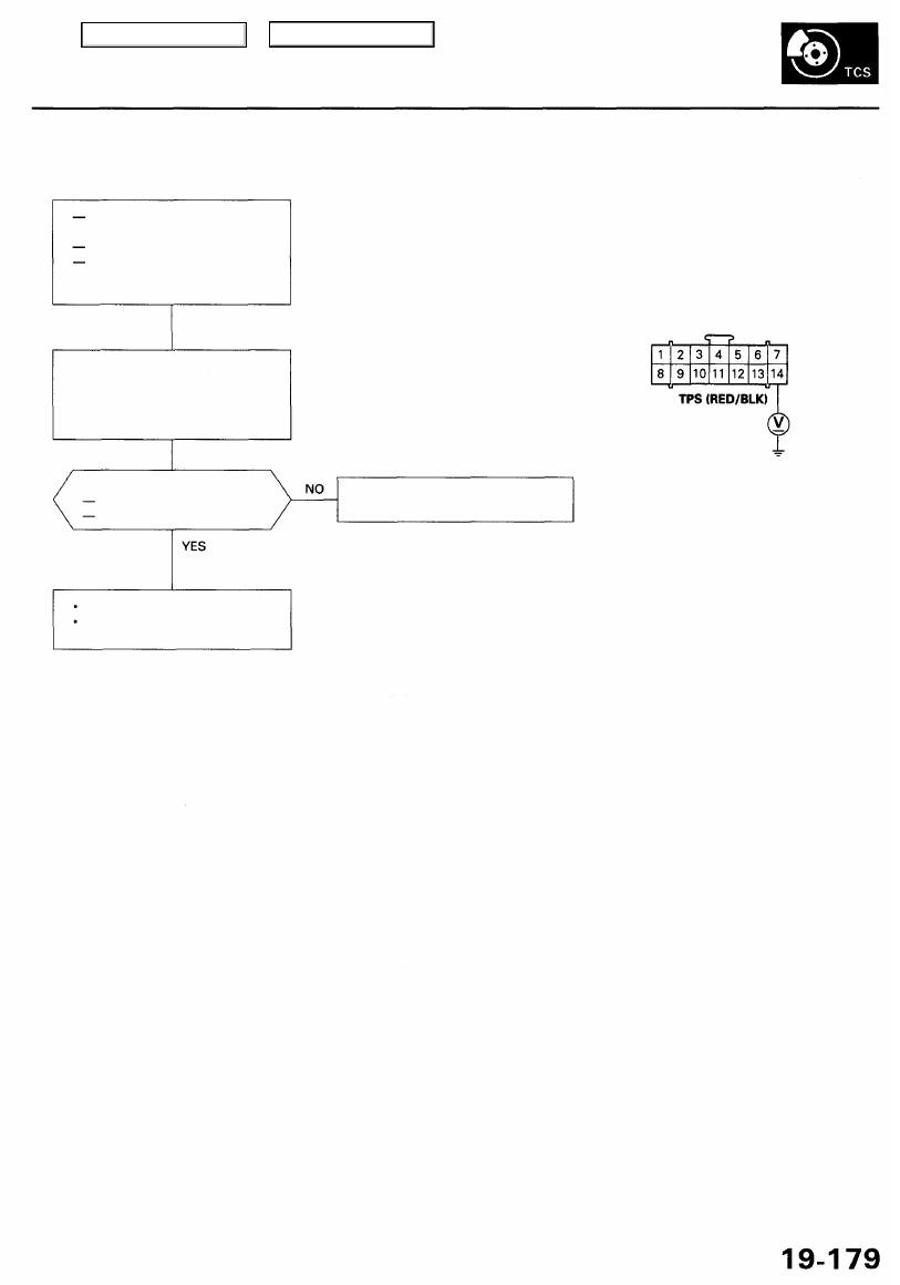
TCS CONTROL UNIT 14P CONNECTOR
Check for an open in the TPS cir-
cuit:
Measure the voltage between the
TCS control unit 14P connector
terminal No. 14 and body ground.
Is the voltage as specified?
Fully closed: about 0.5 V
Fully open: about 4.5 V
Repair open in the wire between
the PCM and TCS control unit.
Wire side of female terminals
The system is OK at this time.
If the problem recurs, replace
the TCS control unit.
Main Menu
Table of Contents
Troubleshooting
TCS Control Valve ( TCV) Sensor Signal
Diagnostic Trouble Code (DTC) 3-7: TCS Control Valve ( TCV) Sensor Signal Diagnosis
With engine running, TCS
indicator light is ON.
MIL is OFF.
With the SCS service connec-
tor connected (see page
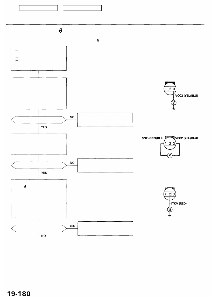
Check for an open in the VCC2
circuit:
1. Disconnect the TCS control
valve sensor connector.
2. Turn the ignition switch ON (II).
3. Measure the voltage between
terminal No. 3 and body
ground.
Is there about 5V?
Check for an open in the SG2 cir-
cuit:
Measure the voltage between the
TCS control valve sensor connec-
tor terminal No. 1 and No. 3.
Is there about B V?
Check for a short to body ground
in the TCV circuit:
1. Turn the ignition switch OFF.
2. Disconnect the TCS control
unit 14P connector.
3. Turn the ignition switch ON (II).
4. Check for continuity between
the TCS control valve sensor
connector terminal No. 2 and
body ground.
NOTE: When both the TCS indicator
light and the MIL are ON, troubleshoot
the PGM-FI system first.
TCS
CONTROL
VALVE
SENSOR
CONNECTOR
Repair open in the wire between
the PCM and TCS control valve
sensor.
Wire side of female terminals
Repair open in the wire between
the PCM and TCS control valve
sensor.
Is there continuity?
Repair short to body ground in
the wire between the TCS control
unit and TCS control valve sensor.
Main Menu
Table of Contents
Нет комментариевНе стесняйтесь поделиться с нами вашим ценным мнением.
Текст