Acura RL (1996-2004 year). Manual — part 619
Lighting System
Combination Light Switch Test
1. Remove the dashboard lower cover (see
).
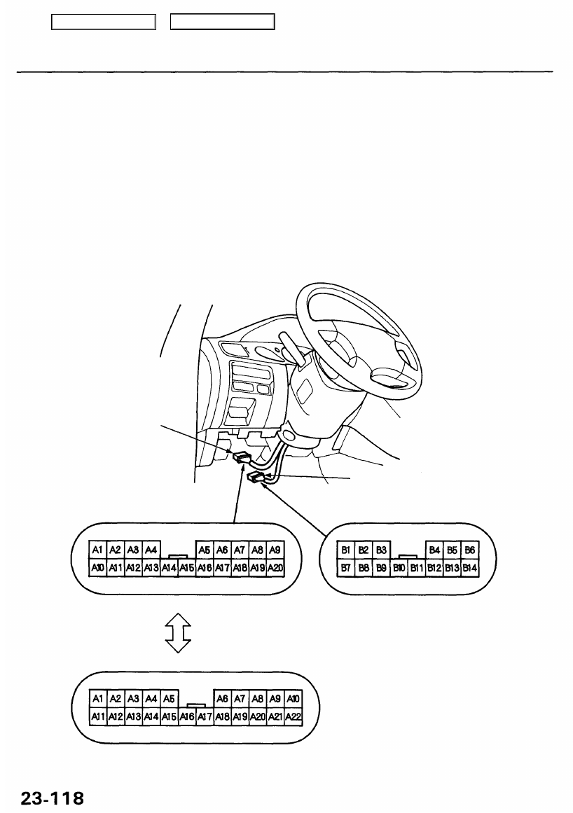
2. Disconnect the 20P (or 22P) and 14P connectors from the main wire harness.
3. Inspect the connector terminals to be sure they are all making good contact.
• If the terminals are bent, loose or corroded, repair them as necessary, and recheck the system.
• If the terminals look OK, check for continuity between them in each switch position according to the table. If there is
no continuity between any of them, check for continuity in the switch harness.
— If there is continuity in the switch harness, replace the combination light switch.
— If there is no continuity in the switch harness, replace it.
14P CONNECTOR
Wire side of female terminals
20P (or 22P) CONNECTOR
'96 - 99 models, '00 - 01 USA models:
'00 - 01 Canada models:
Wire side of female terminals
Main Menu
Table of Contents
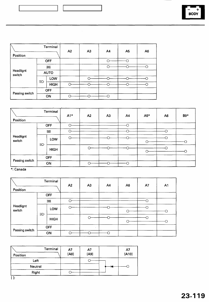
USA (With automatic lighting system):
USA (Without automatic lighting system), '96 - 99 Canada models:
'00 - 01 Canada models:
Turn signal switch:
'00-01 Canada models
Main Menu
Table of Contents
Lighting System
HID Lamp System Troubleshooting ('99 - 04 models)
CAUTION: Never turn on the combination light switch
before fitting the HID bulbs to their bulb sockets and
completing the reassembly of the headlight assembly.
1. Check the No. 45 (20 A) or No. 46 (20 A) fuse in the
under-hood fuse/relay box.
Are the fuses OK?
YES - Go to step 2.
NO - Replace the fuse(s), and recheck.
2. Substitute a known-good HID bulb and recheck.
Does the headlight low beam come on?
YES-Replace the HID bulb.
NO - Go to step 3.
3. Disconnect the 2P connector from the inverter unit.
4. Turn the combination light switch ON.
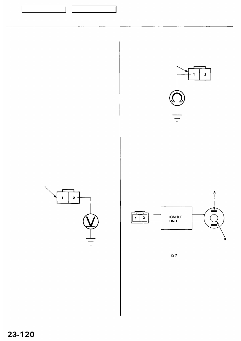
5. Measure voltage between the No. 2 terminal of the
inverter unit 2P connector and body ground.
INVERTER UNIT 2P CONNECTOR
Is there battery voltage?
YES - Go to step 6.
NO - Repair open in the wire between the under-
hood fuse/relay box and the inverter unit.
6. Turn the combination light switch OFF.
YES - Substitute a known-good inverter, and
recheck. If the symptom/indication goes away,
replace the original inverter unit.
NO - Replace the igniter unit.
Is there about 1-2
7. Check for continuity between the No. 1 terminal of
the inverter unit 2P connector and body ground.
INVERTER UNIT 2P CONNECTER
Is there continuity?
YES - Go to step 8.
NO - Repair open in the wire between the inverter
unit and body ground. If the wire is OK, check for
poor ground at G201 or G301.
8. Measure resistance between the No. 1 and B termi-
nal and the No. 2 and A terminal of the igniter unit.
Main Menu
Table of Contents
Headlights
Combination Light Switch
Replacement
1. Remove the dashboard lower cover (see
).
2. Remove the steering column covers (see
).
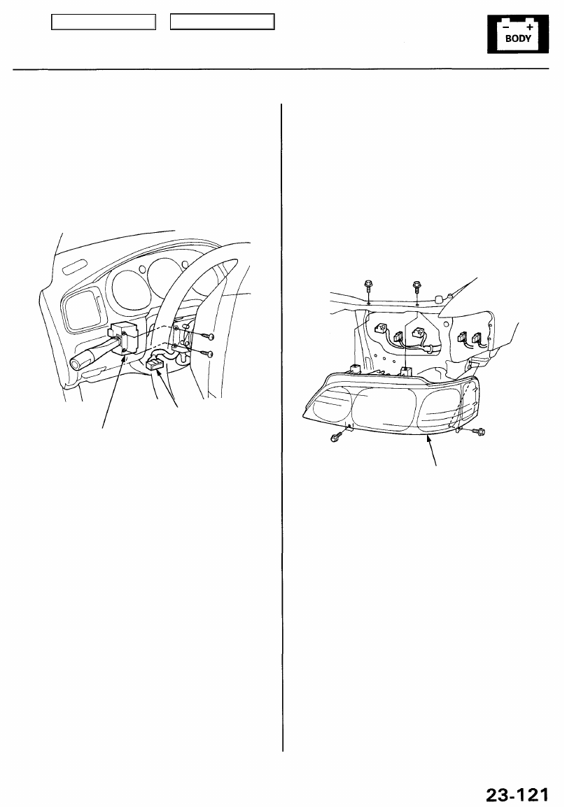
3. Disconnect the 14P connector from the combination
light switch, then remove the two screws and the
switch.
4. Install the combination light switch in the reverse
order of removal.
COMBINATION LIGHT SWITCH
14P CONNECTOR
Replacement
CAUTION: Headlights become very hot in use; do not
touch them or the attaching hardware immediately
after they have been turned off.
1. Remove the front bumper and front bumper upper
beam (see
).
2. Disconnect the connectors.
3. Remove the four mounting bolts, then remove the
headlight assembly.
HEADLIGHT
ASSEMBLY
'96 - 98 models:
HEADLIGHT: 60/55 W
FRONT TURN SIGNAL LIGHT: 21 W
FRONT PARKING LIGHT: 5 W x 2
FRONT FOG LIGHT: 55 W
SIDE MARKER LIGHT: 5 W
'99 - 01 models:
HEADLIGHT LOW BEAM: 35 W
HEADLIGHT HIGH BEAM: 55 W
FRONT TURN SIGNAL/PARKING LIGHT: 27/8 W
SIDE MARKER LIGHT: 5 W
4. Install the headlight in the reverse order of removal.
5. After replacement, adjust the headlights to local
requirements.
Main Menu
Table of Contents
Нет комментариевНе стесняйтесь поделиться с нами вашим ценным мнением.
Текст