Acura RL (1996-2004 year). Manual — part 378
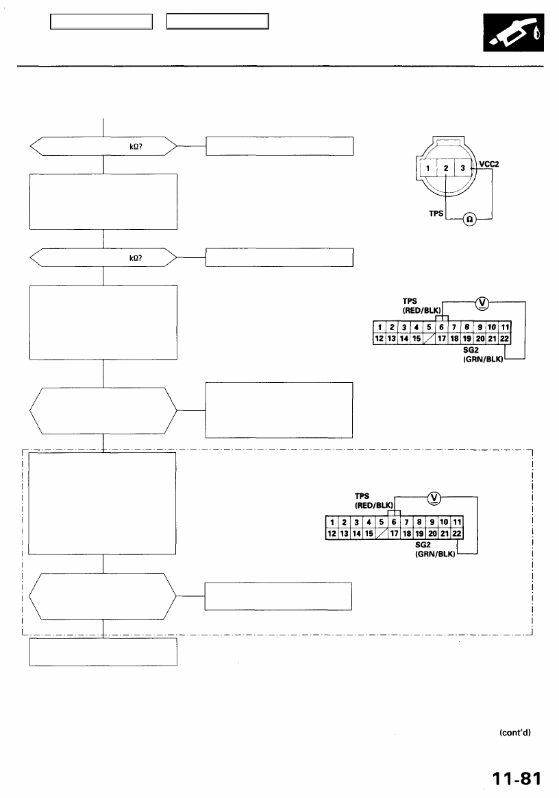
Is there about 0.5
YES
Check for an open or short in the
TP sensor:
Measure resistance between No. 2
terminal and No. 3 terminal with
the throttle fully closed.
Is there about 4.5
YES
Check for an open in the PCM:
1. Reconnect the TP sensor con-
nector.
2. Turn the ignition switch ON (II).
3. Measure voltage between D6
terminal and D22 terminal on
the PCM connector.
Is there approx. 0.5 V when the
throttle is fully closed and
approx. 4.5 V when the throttle
is fully opened?
(with TCS/VSA*)
NO
TP SENSOR
Replace the throttle body.
Replace the throttle body.
Terminal side of male terminals
PCM CONNECTOR D (22P)
Substitute a known-good PCM
and recheck (see page
for
immobilizer information). If pre-
scribed voltage is now available,
replace the original PCM.
Wire side of female terminals
Check for a short in the TCS con-
trol unit:
1. Turn the ignition switch OFF.
2. Disconnect the HP (26P)* con-
nector from the TCS (VSA)*
control unit.
3. Turn the ignition switch ON (II).
4. Measure voltage between D6
terminal and D22 terminal on
the PCM connector.
Is there about 0.5 V when the
throttle is fully closed and
approx. 4.5 V when the throttle
is fully opened?
Replace the TCS control unrt/VSA
converter unit.
NO
*: '00 - 01 models
Repair short in the wire between
PCM (D6) and TP sensor.
YES
YES
NO
NO
Main Menu
Table of Contents
PGM-FI System
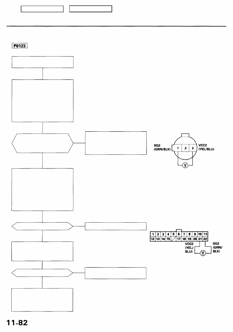
Throttle Position (TP) Sensor (cont'd)
The scan tool indicates Diagnostic Trouble Code (DTC) P0123: A high voltage problem in the Throttle Position
(TP) sensor circuit.
Is there about 0.5 V when
the throttle is fully closed
and approx. 4.5 V when the
throttle is fully opened?
NO
Check for an open in the TP sen-
sor:
1. Turn the ignition switch OFF.
2. Disconnect the TP sensor con-
nector.
3. Turn the ignition switch ON (II).
4. Measure voltage between
No. 3 terminal and No. 1 ter-
minal on the harness side of
the TP sensor connector.
Is there about 5 V?
NO
Check for an open in the wire
(SG2 line):
Measure voltage between PCM
connector terminals D21 and D22.
Is there about 5 V?
NO
Substitute a known-good PCM
and recheck (see page
for
immobilizer information). If pre-
scribed voltage is now available,
replace the original PCM.
TP SENSOR CONNECTOR (C113)
Intermittent failure, system is OK
at this time. Check for poor con-
nections or loose wires at C251,
C253, C254 (located at left shock
tower) C113 (TP sensor) and PCM.
Wire side of female terminals
Replace the throttle body.
PCM CONNECTOR D (22P)
Wire side of female terminals
Repair open in the wire between
PCM (D22) and TP sensor.
YES
YES
YES
Problem verification:
1. Start the engine. Hold the
engine at 3,000 rpm with no
load (in Park or neutral) until
the radiator fan comes on,
then turn the ignition switch
OFF.
2. Turn the ignition switch ON (II).
3. Check the throttle position
with the scan tool.
— The MIL has been reported on.
— DTC P0123 is stored.
Main Menu
Table of Contents
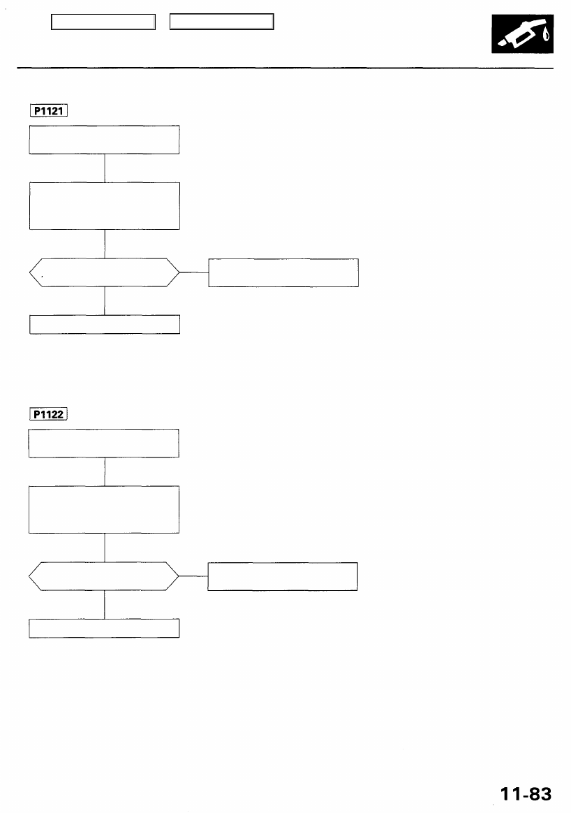
The scan tool indicates Diagnostic Trouble Code (DTC) P1121: Throttle Position (TP) lower than expected.
— The MIL has been reported on.
— DTC P1121 is stored.
Problem verification:
1. Turn the ignition switch ON (II).
2. Check the throttle position
with the scan tool.
s 14.4% or higher indicated when
the throttle is fully opened?
Intermittent failure, system is OK
at this time.
The scan tool indicates Diagnostic Trouble Code (DTC) P1122: Throttle Position (TP) higher than expected.
— The MIL has been reported on.
— DTC P1122 is stored.
Problem verification:
1. Turn the ignition switch ON (II).
2. Check the throttle position
with the scan tool.
Is 19.1% or less indicated when
the throttle is fully closed?
Intermittent failure, system is OK
at this time.
Replace the TP sensor.
NO
YES
Replace the TP sensor.
NO
YES
Main Menu
Table of Contents
PGM-FI System
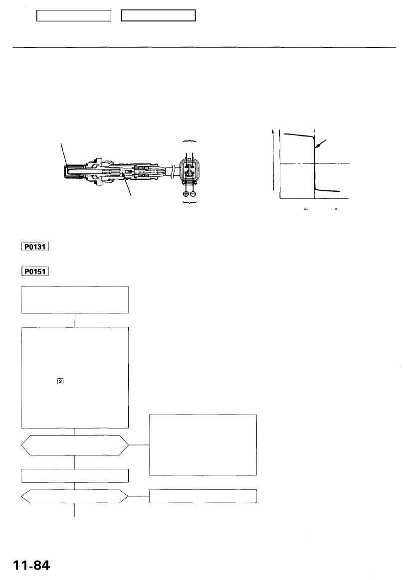
Primary Heated Oxygen Sensor (HO2S) (Sensor 1)
The Heated Oxygen Sensors (HO2S) detect the oxygen content in the exhaust gas and signal the PCM. In operation, the
PCM receives the signals from the sensor and varies the duration during which fuel is injected. To stabilize the sensor's
output, the sensor has an internal heater. The Right Primary HO2S (Bank 1, Sensor 1) is installed in the right exhaust man-
ifold, and the Left Primary HO2S (Bank 2, Sensor 1) is installed in the left exhaust manifold.
ZIRCONIA
ELEMENT
SENSOR
TERMINAL
®e
VOLTAGE (V)
HEATER
STOICHIOMETRIC
AIR-FUEL RATIO
HEATER
TERMINAL
RICH
AIR-
FUEL
RATIO
LEAN
The scan tool indicates Diagnostic Trouble Code (DTC) P0131: A low voltage problem in the Right Primary
Heated Oxygen Sensor (HO2S) (Bank 1, Sensor 1) circuit.
The scan tool indicates Diagnostic Trouble Code (DTC) P0151: A low voltage problem in the Left Primary
Heated Oxygen Sensor (HO2S) (Bank 2, Sensor 1) circuit.
— The MIL has been reported on.
— DTC P0131 and/or P0151 are
stored.
Does the voltage stay at 0.5 V
or less?
Is it normal?
NO
Intermittent failure, system is OK
at this time. Check for poor con-
nections or loose wires at C251,
C254 (located at left shock tower)
C119 (right primary HO2S (Bank
1, Sensor 1)) or C126 (left prima-
ry HO2S (Bank 2, Sensor 1))* and
PCM.
Repair fuel supply system.
*: P0151
NO
YES
Check the fuel pressure.
YES
Problem verification:
1. Do the PCM Reset Procedure.
2. Start the engine. Hold the
engine at 3,000 rpm with no
load (in Park or neutral) until
the radiator fan comes on.
3. Test-drive with the transmis-
sion in position.
4. Check the right primary HO2S
(Bank 1, Sensor 1) or left pri-
mary HO2S* (Bank 2, Sensor
1) output voltage with the scan
tool during acceleration using
wide open throttle.
Main Menu
Table of Contents
Нет комментариевНе стесняйтесь поделиться с нами вашим ценным мнением.
Текст